
Luggage rack

A technology of a luggage rack and a positioning part, which is applied in the field of luggage racks, can solve the problems of troublesome installation, fixed structure, lack of luggage racks, etc., and achieves the effect of avoiding cumbersome and unstable installation.

Pending Publication Date: 2020-01-14
钱为方
View PDF0 Cites 0 Cited by
  • Summary
  • Abstract
  • Description
  • Claims
  • Application Information

AI Technical Summary

Problems solved by technology

[0004] However, for cars driving in urban areas, car owners usually install roof racks on the top of the car to enhance the appearance of the car in order to enhance the appearance of the car. Installation, but the current luggage rack structure is fixed, and the installation is more troublesome. There is a lack of a luggage rack that is quick to install, easy to operate, and lightweight

Method used


Image

  • Luggage rack
  • Luggage rack
  • Luggage rack

Examples


Embodiment Construction

[0023] The implementation of the present application will be described in detail below with reference to the accompanying drawings and examples, so as to fully understand and implement the implementation process of how the present application uses technical means to solve technical problems and achieve technical effects.

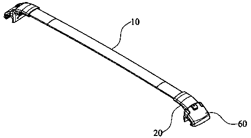
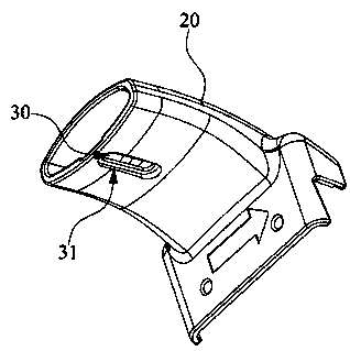
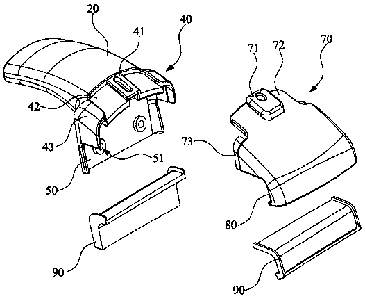
[0024] Please also refer to Figure 1 to Figure 3 , figure 1 It is a three-dimensional view of the luggage rack of the embodiment of the present application; figure 2 It is a schematic diagram of the inner hook part of the embodiment of the present application; image 3 It is a schematic diagram of the separation of the inner hook and the outer hook in the embodiment of the present application. As shown in the figure, a luggage rack is made of stainless steel or aluminum, including a positioning bar 10; inner hooks 20 respectively sleeved at both ends of the positioning bar 10, the inner hooks 20 are located on the lower side of the positioning bar 10 and...


PUM


Abstract

The invention discloses a luggage rack made of stainless steel or aluminum. The luggage rack comprises a positioning transverse rod, inner hook components and outer hook components, wherein the innerhook components are respectively sleeved on two ends of the positioning transverse rod, wherein the inner hook components are located at the lower side of the positioning transverse rod and are provided with movable adjustment holes for mounting rivets; a first extending and positioning part and a first inner hook part are arranged at the top and the bottom of the outer end of each inner hook component; the outer hook components are fixed at the first extending and positioning parts through bolts; each outer hook component is provided with a second extending and positioning part correspondingto the first extending and positioning part and a second outer hook part corresponding to the inner hook part; and the first inner hook parts and the second outer hook parts form clamping openings andare cooperatively clamped on two sides of an automobile roof bracket. The inner hook components are sleeved on two ends of the positioning transverse rod; the outer hook components are fixed throughthe bolts and are clamped and mounted on brackets on two sides of an automobile body, so that the split mounting of the luggage rack is achieved; and the trouble that the previous mounting of the luggage rack is complicated and not stable enough can be avoided.

Description

technical field [0001] The application belongs to the technical field of auto parts, and in particular relates to a luggage rack. Background technique [0002] The roof luggage rack is installed on the top of the car and is used to load large luggage, kayaks, swimming rings and other bulky items. The car with the roof luggage rack is especially convenient when traveling and can meet the different needs of people. [0003] In the past, car owners chose to install roof racks for the purpose of carrying more items during car travel. Therefore, car owners generally install a roof rack made of metal materials to meet the load-bearing requirements of the roof rack. [0004] However, for cars driving in urban areas, car owners usually install roof racks on the top of the car to enhance the appearance of the car in order to enhance the appearance of the car. installation, but the current luggage rack structure is fixed, and the installation is relatively troublesome, lacking a lu...

Claims


Application Information

Patent Timeline
Patent Type & Authority Applications(China)
IPC IPC(8): B60R9/045B60R9/04
CPCB60R9/045B60R9/04
Inventor 钱为方
Owner 钱为方
Learn More