Hand-propelled wheeled vehicle

A push-wheel type, vehicle technology, applied in the field of vehicles, can solve the problems of easy misoperation, difficult control, complicated operation procedures, etc., and achieve the effect of reducing misoperation, reducing turning radius, and simple operation procedures

Pending Publication Date: 2020-01-14
POSITEC POWER TOOLS (SUZHOU) CO LTD
View PDF0 Cites 1 Cited by
  • Summary
  • Abstract
  • Description
  • Claims
  • Application Information

AI Technical Summary

Problems solved by technology

[0004] If the self-driving switch is not turned off, the turning radius of the walk lawn mower will also be large, and it is difficult to control
Therefore, in the process of using the push lawn mower, if the user needs to turn on the spot more often, the user needs to repeatedly operate the self-driving switch, resulting in complicated operation procedures and easy misoperation

Method used


Image

  • Hand-propelled wheeled vehicle
  • Hand-propelled wheeled vehicle
  • Hand-propelled wheeled vehicle

Examples


example 11

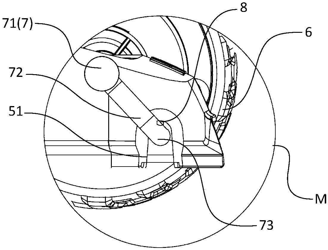
[0080] figure 2 A schematic structural view of a push-wheel vehicle according to an embodiment of the present invention is shown. image 3 show figure 2 Partial enlarged view of M in middle.

[0081] Such as figure 2 and image 3 As shown, the push-wheel vehicle may include: an operating rod 3 , and the operating rod 3 may include a grip portion 1 . Described walking mechanism can comprise front wheel 6 and rear wheel 4, figure 2 The self-driving mechanism is not shown. The push-wheel vehicle can also include: bottom shell 5 and front wheel shaft 7, and described bottom shell 5 comprises the mounting hole (not shown) that supports described front wheel shaft 7; Described front wheel 6 is installed by described front wheel shaft 7 On one side of the bottom shell 5 , the front wheel shaft 7 includes a shaft main body 71 rotatably connected to the front wheel, and the shaft main body 71 can move in the installation hole.

[0082] Such as figure 2 As shown, a second s...

example 12

[0099] In another possible implementation manner, the contact 8 may be located at the top of the installation hole, and a switch trigger part may be provided on the upper side of the shaft main body 71 . In other words, the switch trigger part can be directly disposed on the shaft main body 71 . Figure 8a A schematic diagram showing the structure of contacts and mounting holes according to an embodiment of the present invention, such as Figure 8a As shown, the contact 8 is located on the top of the mounting hole.

[0100] At this time, when the front wheel 6 is above the ground, due to the weight of the front wheel 6 and the shaft body 71, the shaft body 71 moves to the lower side of the installation hole, and the switch trigger part is disconnected from the The connection of the contact 8: when the front wheel 6 touches the ground, due to the weight of the bottom case 5, the shaft main body 71 moves to the upper side of the installation hole, and the switch trigger part is...


PUM


Abstract

The invention relates to a hand-propelled wheeled vehicle. The hand-propelled wheeled vehicle comprises a traveling mechanism, a self-driving mechanism and a first self-driving control device, whereinthe traveling mechanism comprises a front wheel and a rear wheel; the self-driving mechanism is used for driving the traveling mechanism; and the first self-driving control device controls the self-driving mechanism according to whether the front wheel is high off the ground, and when the front wheel is high off the ground, the self-driving mechanism reduces the traveling speed of the traveling mechanism or stops driving the traveling mechanism. When the front wheel is high above the ground through the first self-driving control device, the rotating speed of the self-driving mechanism is controlled, so that the traveling speed of the rear wheel is reduced or the rear wheel is stopped to be driven. According to the hand-propelled wheeled vehicle provided by an embodiment of the invention,the turning radius can be reduced, a self-driving switch does not need to be repeatedly operated during turning, the operation procedure is simple, and misoperation is reduced.

Description

technical field [0001] The invention relates to the technical field of vehicles, in particular to a wheeled vehicle. Background technique [0002] In the process of turning the push-wheel vehicle on the spot, the user needs to tilt the front wheel, and then artificially control the push-wheel vehicle to turn on the spot; if the front wheel is not tilted, the turning radius will be large, Unable to turn in place. [0003] Taking the self-propelled push lawn mower as an example, in the process of turning in place, the front wheels also need to be tilted up, and the self-driving switch needs to be turned off to turn in place, and then the self-driving switch is turned on after the steering is completed. Continue to propel yourself. [0004] If the self-driving switch is not turned off, the turning radius of the walk lawn mower will also be large and difficult to control. Therefore, in the process of using the push lawn mower, if the user needs to turn in situ, the user needs...

Claims


Application Information

Patent Timeline
Patent Type & Authority Applications(China)
IPC IPC(8): A01D34/00A01D69/00A01D75/18
CPCA01D34/006A01D69/00A01D75/18
Inventor 查霞红赵凤丽高彬彬鄢正清
Owner POSITEC POWER TOOLS (SUZHOU) CO LTD
Why Eureka
Try Eureka