Object detection apparatus, object detection method, and object detection program
A technology for object detection and object application in the direction of measuring devices, radio wave measurement systems, and reradiation of sound waves. It can solve problems such as inability to perform correct measurements, and achieve the effects of preventing false detection and improving safety.
- Summary
- Abstract
- Description
- Claims
- Application Information
AI Technical Summary
Problems solved by technology
Method used
Image
Examples
Embodiment approach 1
[0038] ***Description of structure***
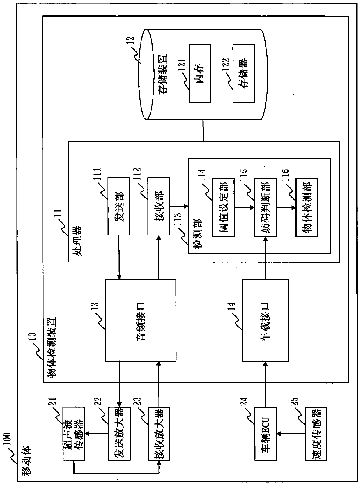
[0039] refer to figure 1 , the configuration of the object detection device 10 according to Embodiment 1 will be described.
[0040] The object detection device 10 is a computer mounted on the mobile body 100 . In Embodiment 1, it is assumed that the mobile body 100 is a vehicle. However, the mobile body 100 may be of other types such as a ship.
[0041] In addition, the object detection device 10 may be integrally or inseparably attached to the mobile body 100 or other illustrated components, or may be detachably or separably attached.
[0042] The object detection device 10 has hardware such as a processor 11 , a storage device 12 , an audio interface 13 , and a vehicle interface 14 . The processor 11 is connected to other hardware via a system bus, and controls these other hardware.
[0043] The processor 11 is an IC (Integrated Circuit) that performs processing. As a specific example, the processor 11 is a CPU (Central Processi...
Deformed example 1
[0125] In Embodiment 1, in Figure 8 In step ST33, the speed of the mobile body 100 is acquired from the speed sensor 25, and changes in the positional relationship between the obstacle signal source 30 and the mobile body 100 are estimated.
[0126] As Modification 1, the obstruction determination unit 115 may estimate the obstruction signal using a sensor such as a laser radar, a millimeter-wave radar, a video camera, a far-infrared camera, or a GPS (Global Positioning System) mounted on the mobile body 100. Changes in the positional relationship between the source 30 and the mobile body 100 . In addition, the obstruction determination unit 115 may obtain information indicating the position and speed of the object through vehicle-to-vehicle communication with vehicles around the mobile body 100, or road-to-vehicle communication with roadside devices around the mobile body 100, Changes in the positional relationship between the obstruction signal source 30 and the moving bod...
Deformed example 2
[0129] In Embodiment 1, each functional component is realized by software. However, as Modification 2, each functional constituent element may be realized by hardware. Regarding this modification 2, points different from Embodiment 1 will be described.
[0130] refer to Figure 13 , the configuration of the object detection device 10 according to Modification 2 will be described.
[0131] When realizing each functional component by hardware, the object detection device 10 has an electronic circuit 15 instead of the processor 11 and the storage device 12 . The electronic circuit 15 is a dedicated circuit that realizes the functions of each functional component and the storage device 12 .
[0132] As the electronic circuit 15, it is assumed that a single circuit, a composite circuit, a programmed processor, a parallel programmed processor, a logic IC, a GA (Gate Array: gate array), an ASIC (Application Specific Integrated Circuit: an integrated circuit for a specific purpose)...
PUM
 Abstract
Description
Claims
Application Information
 - R&D
- Intellectual Property
- Life Sciences
- Materials
- Tech Scout
- Unparalleled Data Quality
- Higher Quality Content
- 60% Fewer Hallucinations
Browse by: Latest US Patents, China's latest patents, Technical Efficacy Thesaurus, Application Domain, Technology Topic, Popular Technical Reports.
© 2025 PatSnap. All rights reserved.Legal|Privacy policy|Modern Slavery Act Transparency Statement|Sitemap|About US| Contact US: help@patsnap.com


