
Light-emitting backlight source of circumferential continuous double-bevel cathode concave-convex arc stack gate control structure

A technology of backlight source and double slope, applied in cold cathode tube, solid cathode, cold cathode manufacturing and other directions, can solve the problems of poor control effect of carbon nanotube cathode, small carbon nanotube cathode production area and high gate voltage

Inactive Publication Date: 2020-01-10
JINLING INST OF TECH
View PDF6 Cites 1 Cited by
  • Summary
  • Abstract
  • Description
  • Claims
  • Application Information

AI Technical Summary

Problems solved by technology

The carbon nanotube layer is composed of many single carbon nanotubes. The carbon nanotube cathode has a small manufacturing area, which means that the number of carbon nanotubes is not large; and there is not enough carbon nanotubes to jointly emit electrons. , it is impossible to provide a large enough cathode current for the light-emitting backlight
Second, the gate voltage has poor control over the carbon nanotube cathode
The specific performance is: sometimes the gate voltage can effectively control the electron emission of the carbon nanotube cathode, and sometimes the electron emission of the carbon nanotube cathode is not restricted by the gate voltage; or, when a sufficient gate voltage is applied Finally, after a sufficiently large electric field strength can be formed, the number of electrons emitted by the carbon nanotube cathode does not change with the change of the gate voltage; or, although the carbon nanotube cathode can emit electrons, the required gate The pole voltage is so high that the subsequent gate voltage cannot continue to change; etc.
Third, the electron emission efficiency of the carbon nanotube cathode is low

Method used


Image

  • Light-emitting backlight source of circumferential continuous double-bevel cathode concave-convex arc stack gate control structure
  • Light-emitting backlight source of circumferential continuous double-bevel cathode concave-convex arc stack gate control structure
  • Light-emitting backlight source of circumferential continuous double-bevel cathode concave-convex arc stack gate control structure

Examples


Embodiment Construction

[0049] The present invention will be further described below in conjunction with the accompanying drawings and embodiments, but the present invention is not limited to this embodiment.

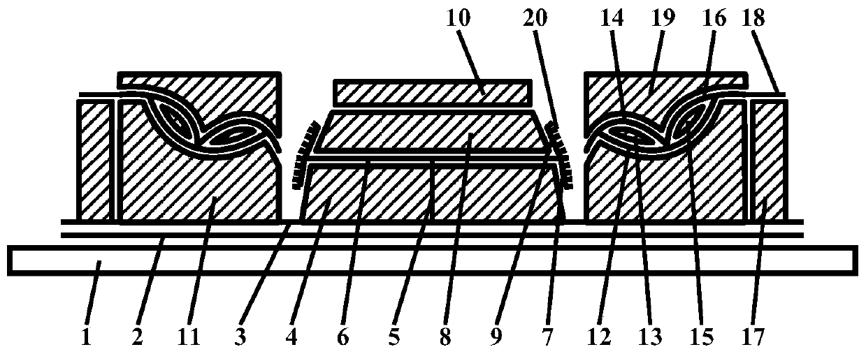
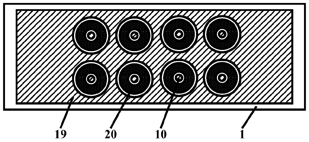
[0050] The light-emitting backlight of the circumferential continuous double-slope cathode concave-convex arc-stacked gated structure of this embodiment is as follows: figure 1 , figure 2 and image 3 As shown, it includes a vacuum enclosure and a getter 25 accessory components located in the vacuum enclosure; the vacuum enclosure is composed of a front transparent hard glass plate 21, a rear transparent hard glass plate 1 and a glass narrow frame strip 26; the front transparent The hard glass plate has an anode light-transmitting film electric layer 22, an anode silver-printed curved line layer 23 and a thin luminescent layer 24, and the anode light-transmissive film electric layer is connected to the anode silver-print curved line layer, and the thin light-emitting layer It is made on the...


PUM


Abstract

The invention discloses a light-emitting backlight source of a circumferential continuous double-bevel cathode concave-convex arc stack gate control structure. The light-emitting backlight source comprises a vacuum sealing body and getter accessory elements located in the vacuum sealing body. The vacuum sealing body is composed of a front transparent hard glass plate, a rear transparent hard glassplate and narrow glass frame strips. The front transparent hard glass plate is provided with an anode light-transmitting film electric layer, an anode silver-printed bent wire layer and a thin light-emitting layer, wherein the anode light-transmitting film electric layer is connected with the anode silver-printed bent wire layer, and the thin light-emitting layer is manufactured on the anode light-transmitting film electric layer. The rear transparent hard glass plate is provided with the circumferential continuous double-bevel cathode concave-convex arc stack gate control structure. The light-emitting backlight source has the advantages of simple manufacturing structure and high light-emitting brightness of the light-emitting backlight.

Description

technical field [0001] The present invention belongs to the fields of plane display technology, integrated circuit science and technology, vacuum science and technology, nanometer science and technology, microelectronic science and technology, optoelectronic science and technology, and semiconductor science and technology. The invention relates to the production of a planar light-emitting backlight source, in particular to the production of a planar light-emitting backlight source with carbon nanotube cathodes, and in particular to a light-emitting backlight source with a circular continuous double-slope cathode concave-convex arc-stacked gate structure and its manufacturing process. Background technique [0002] Carbon nanotubes are tube-shaped substances with nanometer-scale diameters, and their electrical conductivity is very good. In light-emitting backlight products, carbon nanotubes have been used as cathode materials. In a suitable vacuum environment, carbon nanotube...

Claims


Application Information

Patent Timeline
Patent Type & Authority Applications(China)
IPC IPC(8): H01J17/06H01J17/04H01J17/12H01J17/38H01J17/48H01J9/02H01J9/20
CPCH01J9/02H01J9/025H01J9/20H01J17/04H01J17/066H01J17/12H01J17/38H01J17/48
Inventor 李玉魁
Owner JINLING INST OF TECH
Learn More