
Overheating power cutoff method for switch and electric equipment

A technology for electrical equipment and overheating, which is applied to parts of tumbler/rocker switches and parts of thermal switches, etc. It can solve problems such as incomplete contact of sockets, incomplete insertion, and temperature difference between bimetallic strips. achieve costly improvements

Active Publication Date: 2020-01-10
易湘云
View PDF19 Cites 0 Cited by
  • Summary
  • Abstract
  • Description
  • Claims
  • Application Information

AI Technical Summary

Problems solved by technology

[0007] 1. The metal pins of the plug are severely oxidized, and the metal pins are covered with oxides. When the plug is inserted into the socket, the oxide with poor conductivity will increase the resistance and the socket will overheat.
[0008] 2. When the metal pin of the plug is inserted into the socket, the insertion is not complete, resulting in only partial contact, and the too small contact area causes the socket to overheat
[0009] 3. The metal pins of the plug are deformed or worn, resulting in incomplete contact when inserted into the socket, and too small contact area causes the socket to overheat
[0010] 4. The metal pins of the plug or the metal sheet of the socket are stained with foreign matter, such as dust or dirt, which makes the conductivity poor, so the resistance becomes larger and overheats
[0013] Since there are many situations that cause the socket to overheat, and the distance between the socket and the bimetal of the overload protection switch will cause a huge temperature difference, in order to effectively achieve overheat protection, an overload protection should be set on each socket of the extension cord socket. Protection switch, but the price of the bimetal type overload protection switch is relatively high. If it is installed on each socket of the extension cord socket, the price will rise sharply, which is not conducive to popularization.

Method used


Image

  • Overheating power cutoff method for switch and electric equipment
  • Overheating power cutoff method for switch and electric equipment
  • Overheating power cutoff method for switch and electric equipment

Examples


Embodiment Construction

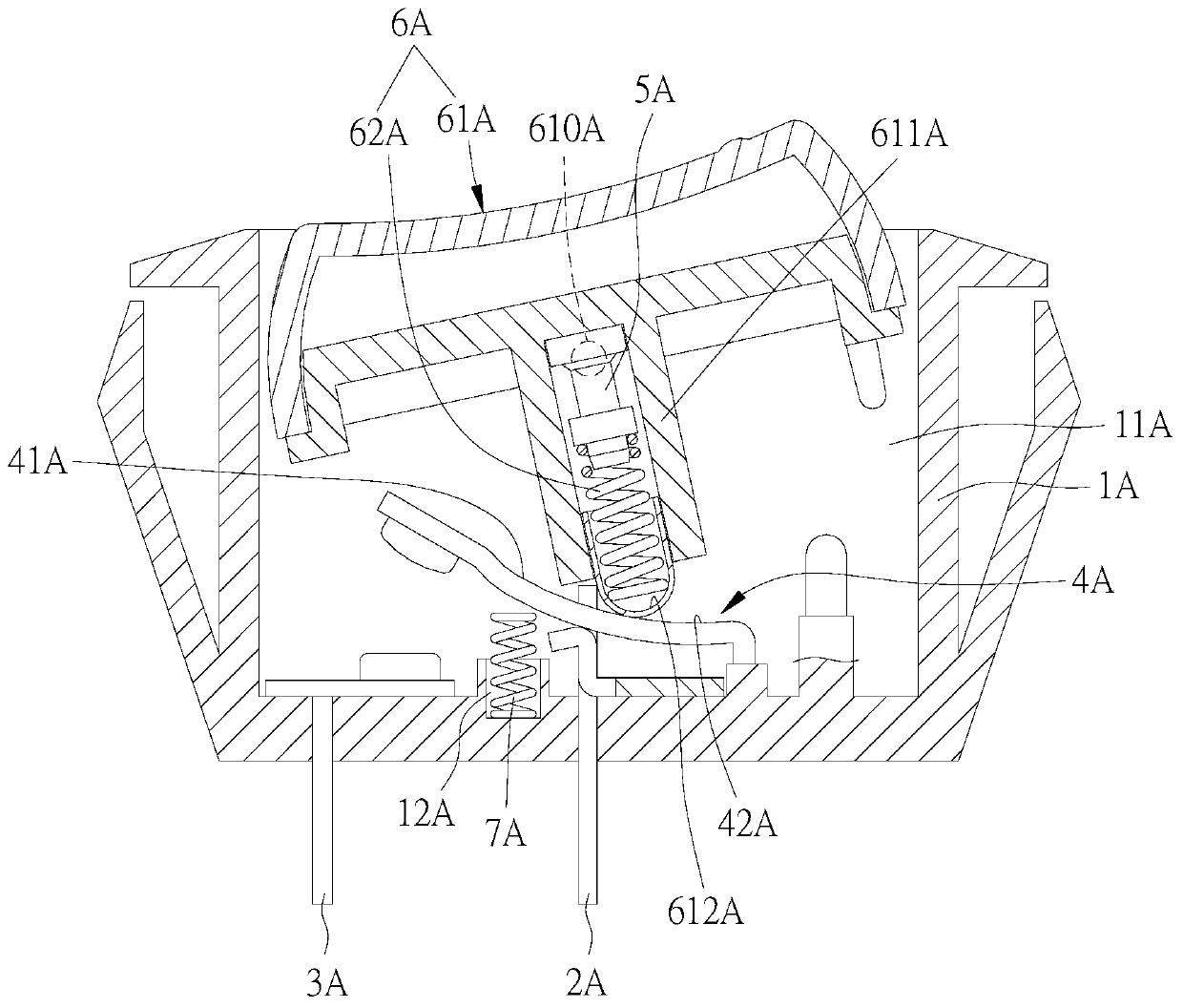
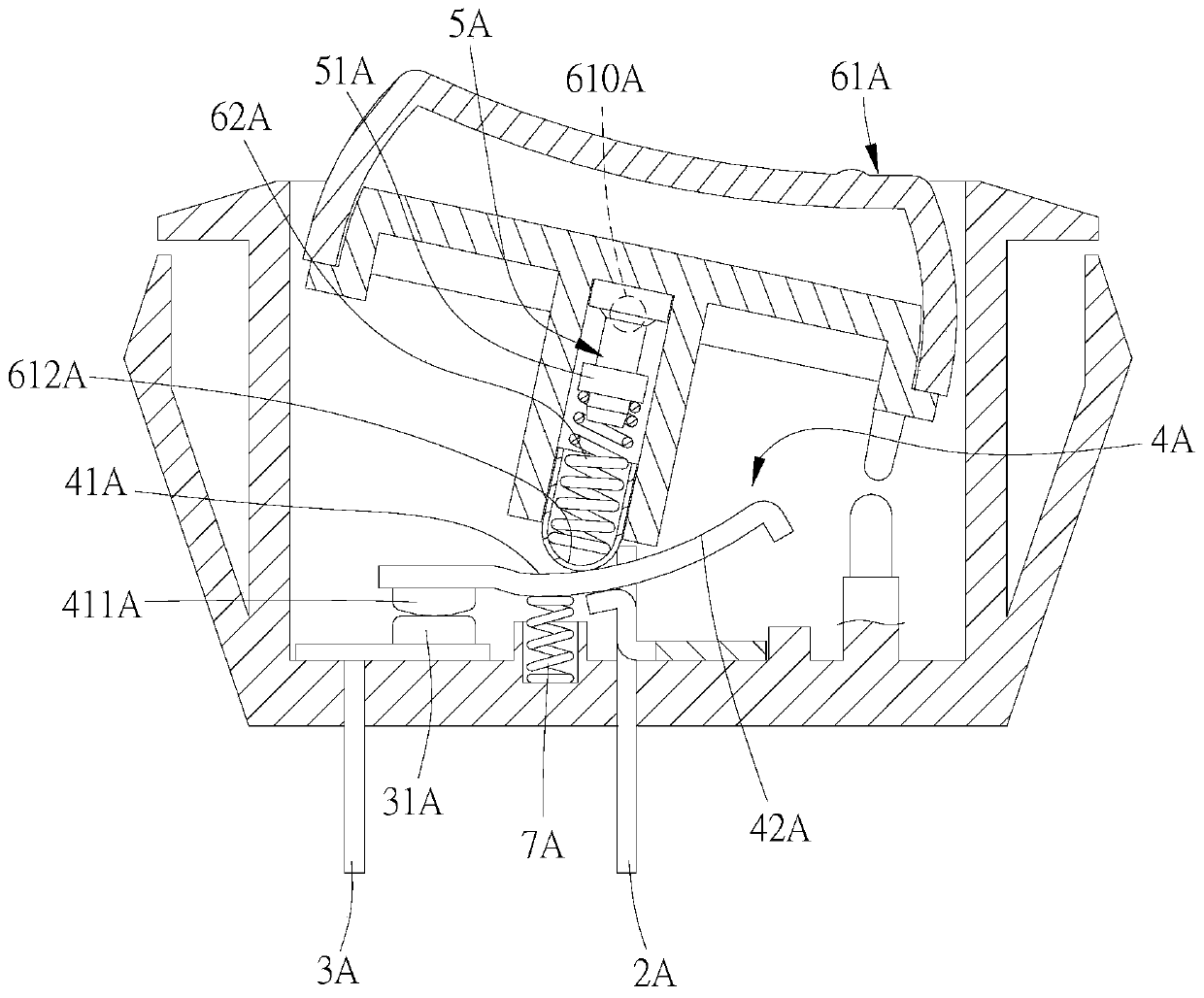
[0058] In view of the above technical features, the main effects of the method for overheating and power-off of a switch or an electrical device of the present invention will be clearly presented in the following embodiments.

[0059] In the cross-sectional views presented in the following embodiments, the relevant operating states and torques are described as follows:

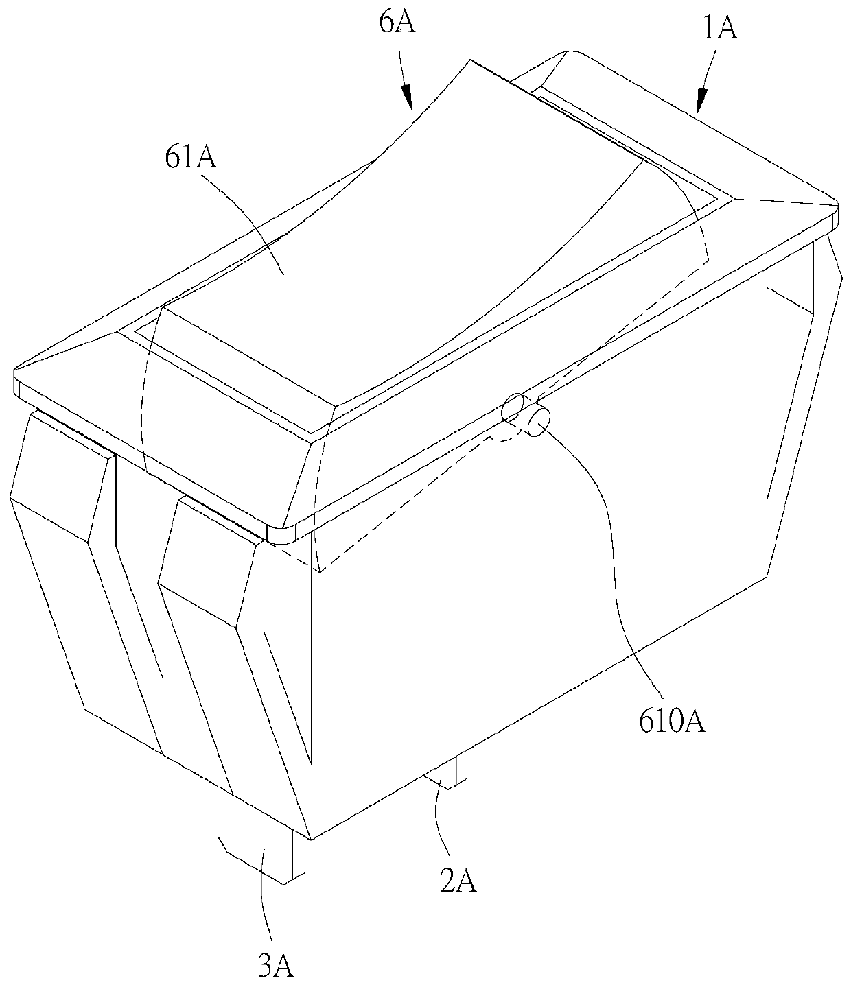
[0060] The operating members (61A, 61B, 61C, 61D, 61E, 61F, 61G) of the rocker switch can be switched to an open position and a closed position.

[0061] Power-off torque refers to when the operating member (61A, 61B, 61C, 61D, 61E, 61F, 61G) is in the closed position, the first elastic force acts on the movable conductive member (4A, 4B, 4C, 4D, 4E, 4F, 4G) ), so that the movable conductive parts (4A, 4B, 4C, 4D, 4E, 4F, 4G) have a clockwise rotation trend around the fulcrum of the first conductive parts (2A, 2B, 2C, 2D, 2E, 2F, 2G) torque.

[0062] The first torque refers to when the operating member (61A,...


PUM


Abstract

The invention provides an overheating power cutoff method for a switch and electric equipment. The method comprises following step: applying a first torque and a second torque on a movable conductivemember so as to conduct a first conductive member and a second conductive member to form a loop, wherein the first torque is opposite to the second torque, and the first torque is greater than the second torque. When an overheating destructive member is destroyed, the first torque is smaller than the second torque, due to the second torque, the movable conductive member leaves from the second conductive member, and the first conductive member and the second conductive member are in a turnoff state.

Description

technical field [0001] The present invention relates to an overheating power-off method for switches or electrical equipment, in particular to a power-off method which is different from fuses and bimetallic strips. The method of destroying and de-energizing the switch is performed by means of thermal energy transfer. Background technique [0002] The existing rocker switch is to control the switch to reciprocately pivot within a certain angle range to control the access and disconnection of the switch. The locating feature locates it in a first position or a second position to form a via or break. [0003] Taiwan Patent No. 321352 "Online Switch Structure Improvement" discloses a switch structure with a fuse, but the fuse is located in the path of the power live wire and needs to rely on the passage of current to have a protective effect, especially for overloaded current to have a chance To blow the fuse, since the fuse needs to allow current to pass through when it is wo...

Claims


Application Information

Patent Timeline
Patent Type & Authority Applications(China)
IPC IPC(8): H01H23/02H01H37/32
CPCH01H23/02H01H37/32
Inventor 易湘云
Owner 易湘云
Learn More