
Oil injection float valve for petroleum drilling

A technology of oil drilling and oil injection, which is applied in earthwork drilling, wellbore flushing, wellbore/well parts, etc. It can solve problems such as plastic deformation of valve sleeves, easy occurrence of sand sticking, increase of piston action resistance, etc., and improve strength , Improve the sealing effect and pressure resistance, and reduce the resistance

Active Publication Date: 2020-01-10
东营市创元石油机械制造有限公司
View PDF6 Cites 2 Cited by
  • Summary
  • Abstract
  • Description
  • Claims
  • Application Information

AI Technical Summary

Problems solved by technology

[0005] Chinese patent CN107152544A (an invention patent application previously submitted by our company) discloses an oil injection float valve for oil drilling. There is a floating oil chamber, which is filled with high-temperature lubricating oil or high-temperature lubricating grease. There are grit chambers, double sealing pairs and a protection step for sealing pairs on the mud channel. There are also limiting platforms and protective tubes to protect the return spring. , The necking body of the float valve is made of high hardness and high wear resistance materials, with simple structure, high strength, good safety performance, high reliability, strong erosion resistance, long service life, easy operation, low cost of use and maintenance However, after the above-mentioned oil injection valve for oil drilling is processed and assembled, the pressure resistance performance is verified from the lower part of 105Mpa. During use, when the pump is turned on, the mud flows down from the upper part, and the piston is pushed to overcome the spring force and move down to open the mud channel; When the pump is stopped, the piston moves up under the action of the spring force to close the mud channel; the following two problems were found during the pressure test: (1) The O-ring at the lower part of the piston was damaged during the pressure test, and the outer edge was torn (2) During use, mud and sand are deposited in the smaller annular gap between the piston and the valve sleeve above the upper O sealing ring, increasing the piston's action resistance , prone to sand stuck

Method used


Image

  • Oil injection float valve for petroleum drilling
  • Oil injection float valve for petroleum drilling
  • Oil injection float valve for petroleum drilling

Examples


Embodiment 1

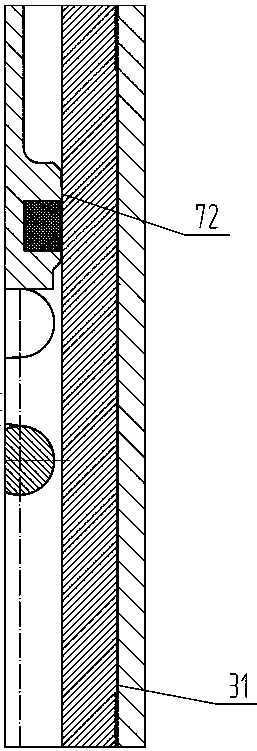
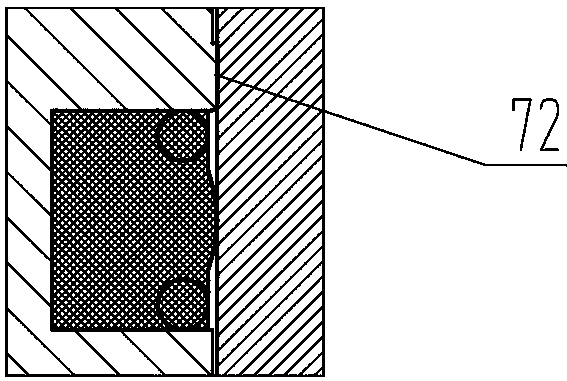
[0033] refer to Figure 1-5 , an oil injection float valve for oil drilling, its main structure is as follows:

[0034] The oil injection float valve includes the oil injection float valve casing 1 and the fixed seat 11 and the valve sleeve 3 which are connected sequentially from top to bottom inside it; the upper end of the fixed seat 11 is open and the lower end is closed. They are connected to each other and form a first annular cavity 16 between the outer walls of the two and the oil injection floating valve housing 1, and the inner cavity of the fixed seat 11 is provided with one or more first holes 17 that communicate with the first annular cavity 16 , the upper inner cavity of the valve sleeve 3 is provided with one or more second holes 18 that communicate with the first annular cavity 16 .

[0035]A stepped oil filling piston 7 and a protective tube 15 connected to each other are installed in the valve sleeve 3 from top to bottom; the stepped oil filling piston 7 is a...

Embodiment 2

[0045] refer to Figure 1-5 , an oil injection float valve for oil drilling, on the basis of the technical solution disclosed in Embodiment 1, it also includes: the fixed seat 11 and the valve sleeve 3 are fixed together by radially arranged slotted headless screws 13, that is, the present The straight pin or hexagon socket cap screw in the prior art is replaced by the slotted headless screw 13. Due to its headless thread structure, it can ensure the fixing effect while occupying less space and less exposed area, which can improve the erosion resistance.

Embodiment 3

[0047] refer to Figure 1-5 , an oil injection float valve for oil drilling, on the basis of the technical solution disclosed in embodiment 1 or 2, also includes: Y-shaped sealing ring 10, S-shaped sealing ring 6 are all made of elastic memory composite material, valve sleeve 3 and stepped The oil injection piston 7 is made of shape memory composite material. Its working principle in this valve is: Y-shaped sealing ring 10, S-shaped sealing ring 6, valve sleeve 3 and stepped oil filling piston 7 will be deformed during pressure test or work, and elastic memory composite materials and shape memory materials are used respectively. Composite materials can restore the original dimensional accuracy after pressure test or work, improve product use effect and prolong service life.


PUM


Abstract

The invention discloses an oil injection float valve for petroleum drilling. An O-shaped ring with poor pressure resistance is replaced by an S-shaped ring with a rectangular section, an arc-shaped sealing surface, annular supporting springs on two sides and high hardness, a high-pressure table is additionally arranged, so that the sealing gap is reduced, and the pressure resistance of the sealingring is improved; the pressed part of a valve bush is internally thickened, an anti-deformation table is additionally arranged, and the gap between the portion and a shell of the oil injection floatvalve is reduced. By means of the combined design, the strength of the whole device is improved, and the sealing effect and the pressure resistance are greatly improved; and meanwhile, a sand prevention seam is additionally arranged, and the O-shaped sealing ring is replaced by a Y-shaped ring with the self-cleaning function, so that the action resistance of a piston is greatly reduced, and the accident rate of sand clamping is reduced.

Description

technical field [0001] The invention relates to the technical field of blowout prevention tools in well drilling in the oil industry, in particular to an oil injection float valve for oil well drilling. Background technique [0002] In oil, natural gas and other drilling and workover operations, in order to prevent the mud in the annulus from returning to the drill string and spraying on the drill floor when connecting a single root or tripping out the drill, at the same time, in order to prevent the bottom fluid from Under the action of entering the drilling tool, overflow, well kick or blowout occurs, and a drilling tool float valve is connected at the bottom of the drill string. [0003] Commonly used drilling tool float valves include arrow type drilling tool float valve and plate type drilling tool float valve. When the pump is turned on, the mud pressure pushes the arrow type valve core to move down or the valve plate flips to open the mud channel. When the pump is sto...

Claims


Application Information

Patent Timeline
IPC IPC(8): E21B21/10
CPCE21B21/10
Inventor 朱怀军田皎雨王笑笑田相录
Owner 东营市创元石油机械制造有限公司
Learn More