
Robot slag-dredging system

A technology of robot and robot body, which is applied in the direction of coating, metal material coating process, hot-dip plating process, etc., can solve the problems of low slag removal efficiency and cannot completely replace manual slag removal, and achieve the effect of improving slag removal efficiency

Pending Publication Date: 2020-01-10
湖南华菱涟钢特种新材料有限公司 +1
View PDF4 Cites 5 Cited by
  • Summary
  • Abstract
  • Description
  • Claims
  • Application Information

AI Technical Summary

Problems solved by technology

[0003] The main purpose of the present invention is to provide a robot slag removal system, which aims to solve the problem that the existing robot slag removal system cannot completely replace manual slag removal due to low slag removal efficiency.

Method used


Image

  • Robot slag-dredging system
  • Robot slag-dredging system
  • Robot slag-dredging system

Examples


Embodiment Construction

[0028] The following will clearly and completely describe the technical solutions in the embodiments of the present invention with reference to the accompanying drawings in the embodiments of the present invention. Obviously, the described embodiments are only part of the embodiments of the present invention, not all of them. Based on the embodiments of the present invention, all other embodiments obtained by persons of ordinary skill in the art without creative efforts fall within the protection scope of the present invention.

[0029] It should be noted that all directional indications (such as up, down, left, right, front, back...) in the embodiments of the present invention are only used to explain the relationship between the components in a certain posture (as shown in the accompanying drawings). Relative positional relationship, movement conditions, etc., if the specific posture changes, the directional indication will also change accordingly.

[0030] In addition, in t...


PUM


Abstract

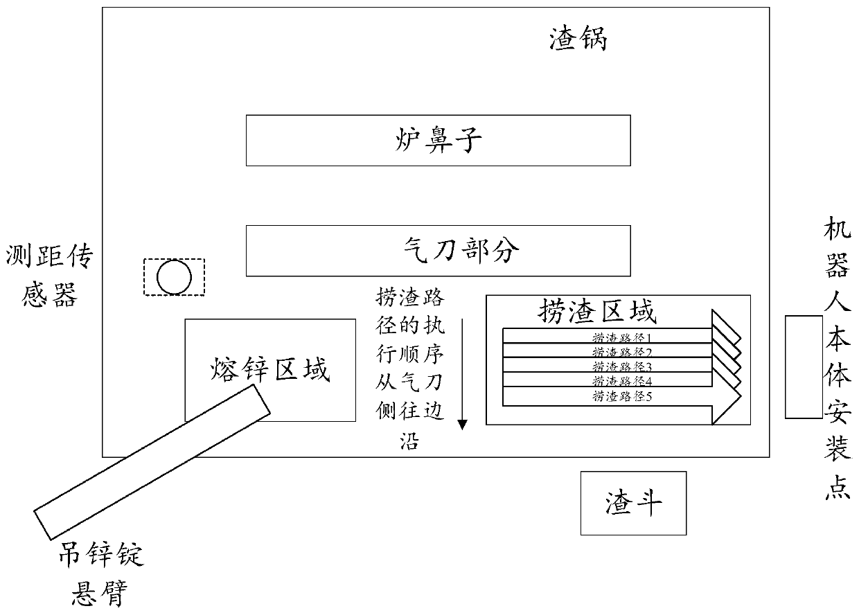
The invention provides a robot slag-dredging system. The robot slag-dredging system comprises a main controller, a robot controller, a robot body, a slag pot, a slag hopper and a distance-measuring sensor. A slag-dredging scoop is installed on the robot body. The main controller is connected with the robot controller. The main controller is connected with the distance-measuring sensor. The robot body is driven to dredge floating slag in the slag pot according to the slag-dredging route in the slag-dredging period by the robot controller under control of the main controller and pour the floating slag into the slag hopper. The distance-measuring sensor is used for measuring the liquid level height in the slag pot before the slag-dredging period and generating liquid level signals and sendingthe liquid level signals to the main controller. The liquid level height value is calculated according to the liquid level signals by the main controller and sent to the robot controller. The slag-dredging route is calculated according to the liquid level height value and the preset teaching route by the robot controller. By means of the technical scheme of the robot slag-dredging system, the slag-dredging effect can be kept at the optimal state, slag-dredging efficiency is improved, and manual slag dredging can be replaced.

Description

technical field [0001] The invention relates to the technical field of thermal coating, in particular to a robot slag removal system. Background technique [0002] The galvanized zinc pot is the key equipment in the continuous surface hot-dip galvanizing process of the cold-rolled steel strip. During the galvanizing process of the steel strip, the floating scum generated in the galvanized pot will adhere to the surface of the steel strip, resulting in the galvanized sheet. Surface quality defects. In order to minimize this defect, it is necessary to remove the scum generated in the zinc pot in time. At present, most steel mills in China use manual slag removal at regular intervals. The on-site employees of the galvanizing unit need to be exposed to the harsh environment of high temperature, dust and noise damage for a long time to carry out arduous slag removal operations. There are a lot of occupational hazards. Therefore, robots are used instead of manual slag removal. S...

Claims


Application Information

Patent Timeline
Patent Type & Authority Applications(China)
IPC IPC(8): C23C2/06C23C2/30C23C2/40
CPCC23C2/003C23C2/06C23C2/30C23C2/40
Inventor 张新建刘杰中冯力力
Owner 湖南华菱涟钢特种新材料有限公司
Learn More