an ozone generator
An ozone generating device and chip technology, which is applied in the direction of ozone preparation, circuit devices, battery circuit devices, etc., can solve the problems of changing the sterilization mode and the difficulty of effectively guaranteeing the sterilization effect, etc.
- Summary
- Abstract
- Description
- Claims
- Application Information
AI Technical Summary
Problems solved by technology
Method used
Image
Examples
Embodiment 1
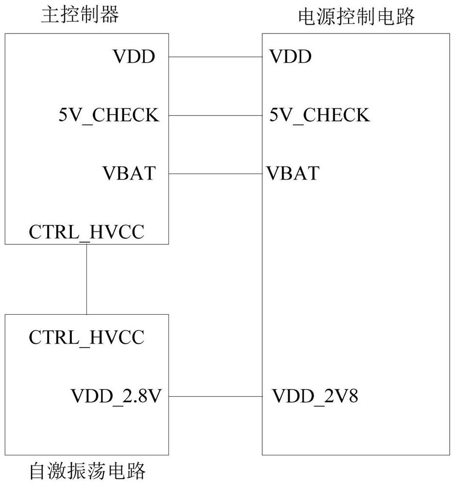
[0040] figure 1 A schematic diagram of an ozone generating device according to Embodiment 1 of the present invention is shown. refer to figure 1 , the ozone generating device of the present embodiment includes: a main controller, a self-excited oscillation circuit and a power control circuit;
[0041] The power input end of the main controller is used to connect the first power output end of the power control circuit, the charging detection input end of the main controller is connected with the charging detection output end of the power control circuit, and the main controller The battery detection input terminal of the main controller is connected to the battery detection output terminal of the power supply control circuit, and the boost control signal output terminal of the main controller is connected to the control signal input terminal of the self-excited oscillation circuit;
[0042] The power input end of the self-excited oscillation circuit is used to connect the sec...
Embodiment 2
[0048] This embodiment is a further improvement on the main controller on the basis of the ozone generating device given in Embodiment 1.
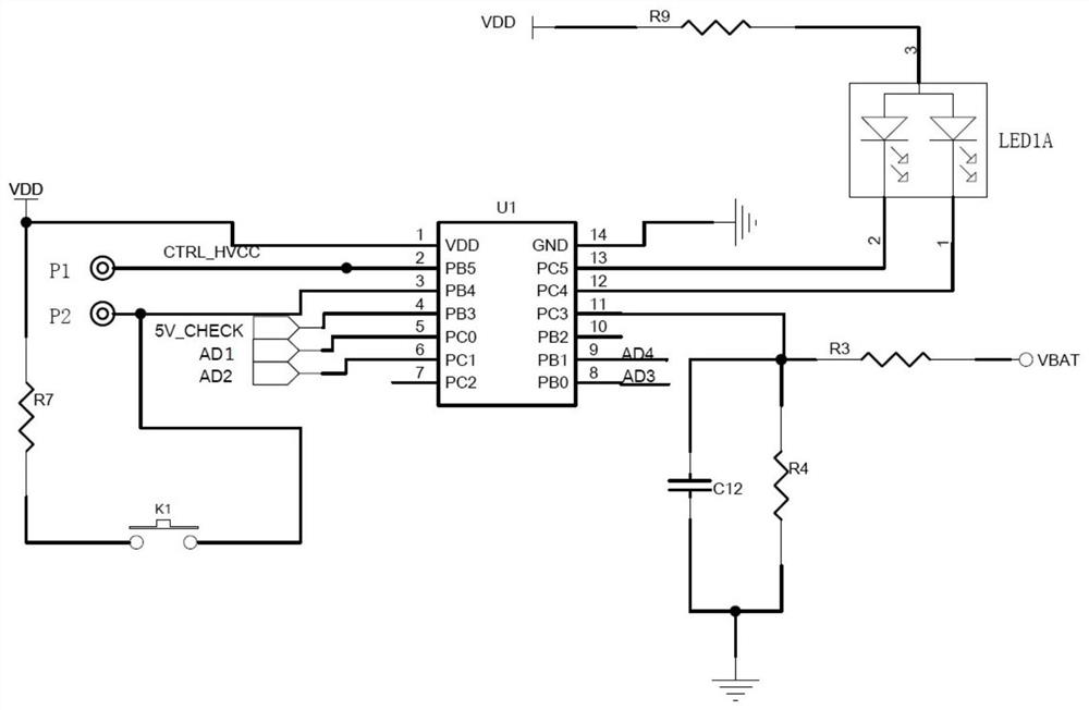
[0049] figure 2 The schematic circuit diagram of the main controller in the ozone generating device of the present embodiment is shown, which can be regarded as figure 1 A specific implementation of the illustrated embodiment. refer to figure 2 , the main controller includes a first chip U1, a third resistor R3, a fourth resistor R4, a seventh resistor R7, a twelfth capacitor C12 and a key K1. The first chip U1 may be an SQ2711 chip.
[0050] The pin 1 of the first chip U1 is the positive pole of the power supply, which is connected to the power input terminal VDD of the main controller.
[0051] The pin 2 of the first chip U1 is a CTRL_HVCC network terminal, which is used for high-voltage boost control of sterilization, and is connected with the boost control signal output terminal of the main controller.
[0052] The pin 3 of the ...
Embodiment 3
[0064] This embodiment is a further improvement on the self-excited oscillation circuit on the basis of the ozone generating device given in Embodiment 2.
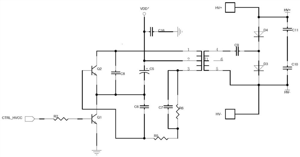
[0065] refer to image 3 , the self-excited oscillation circuit includes a transformer, a first peripheral circuit on the input side of the transformer, and a second peripheral circuit on the output side of the transformer;
[0066] The first peripheral circuit of the self-excited oscillation circuit includes a first transistor Q1, a second transistor Q2, a second resistor R2, a fifth capacitor C5, a sixth capacitor C6, a seventh capacitor C7, an eighth capacitor C8 and a Sixteen capacitors C16.
[0067]The base of the first transistor Q1 is connected to the control signal input terminal CTRL_HVCC of the self-excited oscillation circuit through the second resistor R2, the emitter of the first transistor Q1 is grounded, and the collector of the first transistor Q1 is connected to The emitter of the second transistor Q2 is...
PUM
 Abstract
Description
Claims
Application Information
 - R&D
- Intellectual Property
- Life Sciences
- Materials
- Tech Scout
- Unparalleled Data Quality
- Higher Quality Content
- 60% Fewer Hallucinations
Browse by: Latest US Patents, China's latest patents, Technical Efficacy Thesaurus, Application Domain, Technology Topic, Popular Technical Reports.
© 2025 PatSnap. All rights reserved.Legal|Privacy policy|Modern Slavery Act Transparency Statement|Sitemap|About US| Contact US: help@patsnap.com


