Eureka AIR delivers breakthrough ideas for toughest innovation challenges, trusted by R&D personnel around the world.

Multi-angle micro-shape cutting machining device and machining method

A cutting and multi-angle technology, which is applied to the processing of multi-angle micro-shape cutting devices, the processing of cutting devices, and the fields of multi-angle micro-shape cutting devices, can solve the problem of difficult control of cutting depth, workpiece displacement, and inconvenient operation. and other problems to achieve the effect of improving functionality, ease of use, and improving practicability

Active Publication Date: 2020-01-10
CHANGSHA AERONAUTICAL VACATIONAL AND TECHNICAL COLLEGE +1
View PDF8 Cites 6 Cited by
  • Summary
  • Abstract
  • Description
  • Claims
  • Application Information

AI Technical Summary

Problems solved by technology

[0003] While the traditional cutting device is working, although the angle of the cutting head can be changed in the process of processing for bevel cutting, but because the workpiece has multiple faces, it is necessary to adjust the position of the workpiece in the process of cutting multiple bevels, especially It is inconvenient to do it during the cutting of plate-shaped workpieces. At the same time, during the cutting process, the position of the object needs to be moved for cutting larger objects. Manually moving the object will not only easily cause the workpiece to shift, but also inconvenient to operate. In the cutting process of traditional devices, it is difficult to control the cutting depth manually. Therefore, a multi-angle micro-shape cutting device and processing method are designed to solve the above problems.

Method used


Image

  • Multi-angle micro-shape cutting machining device and machining method
  • Multi-angle micro-shape cutting machining device and machining method
  • Multi-angle micro-shape cutting machining device and machining method

Examples


Embodiment Construction

[0033] In order to make the technical solutions of the present invention clearer and clearer to those skilled in the art, the present invention will be further described in detail below in conjunction with the examples and accompanying drawings, but the embodiments of the present invention are not limited thereto.

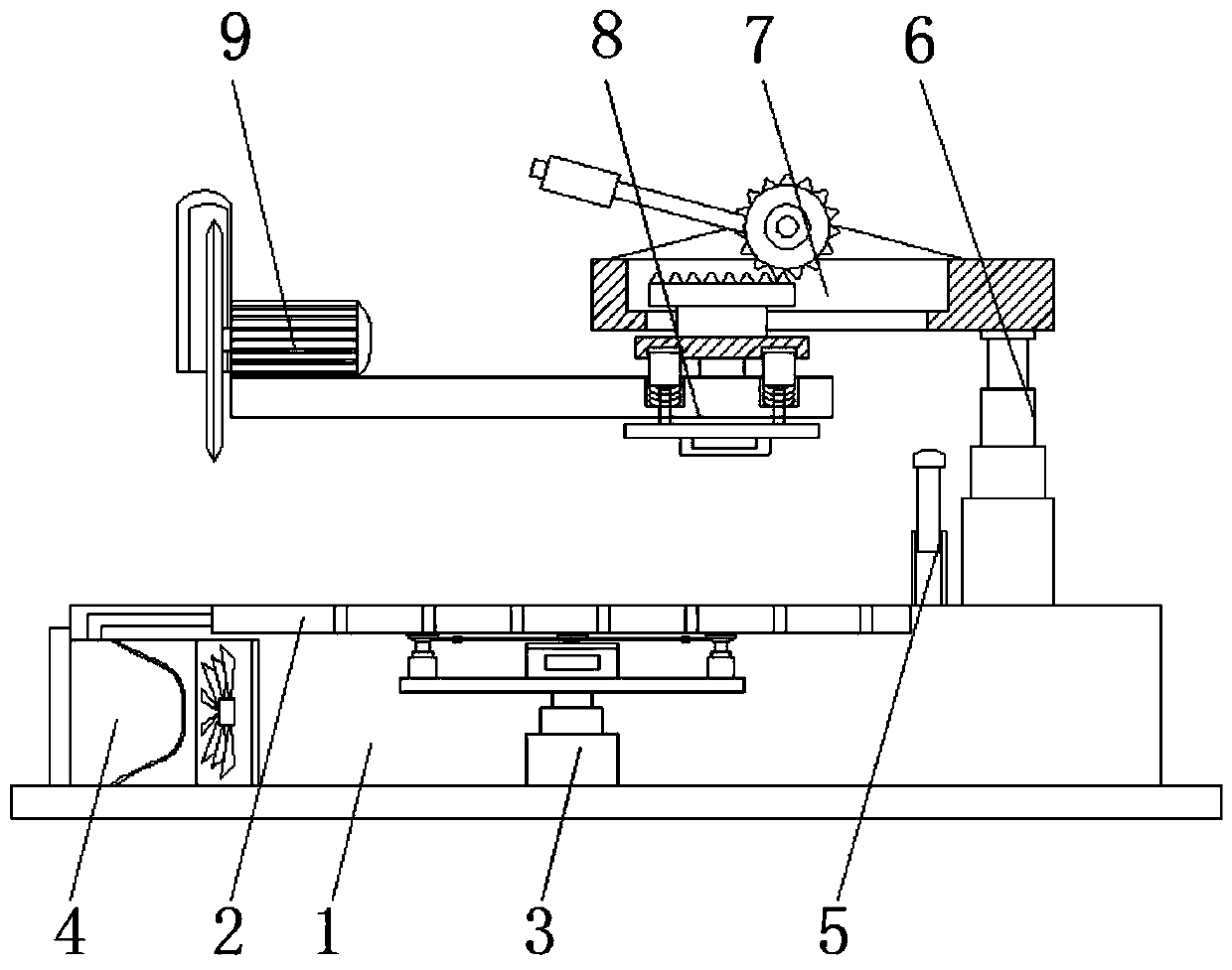
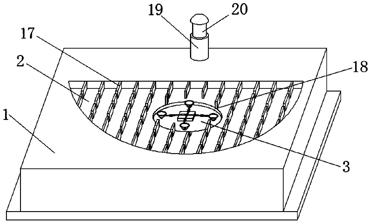
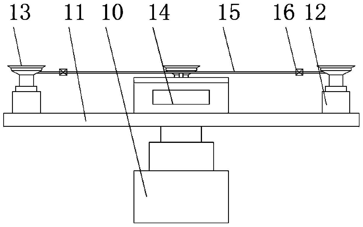
[0034] Such as Figure 1-Figure 8 As shown, a multi-angle micro-shape cutting device provided in this embodiment includes a base 1, a cutting groove 2 is opened on the top of the base 1, and a workpiece angle adjustment and fixing mechanism 3 is installed inside the base 1, and the workpiece angle is adjusted and fixed. The top of the mechanism 3 extends to the inside of the cutting groove 2, a collection bin 4 is installed on one side of the base 1, and a limit mechanism 5 is fixed on the side of the top of the base 1 away from the collection bin 4, and the top of the base 1 is close to the limit mechanism 5. One side is equipped with a first telescopic cylinder 6...


PUM


Abstract

The invention discloses a multi-angle micro-shape cutting machining device and machining method, and belongs to the technical field of cutting devices. The multi-angle micro-shape cutting machining device comprises a base, wherein a cutting groove is formed in the top of the base, and a workpiece angle adjustment and fixation mechanism is installed in the base; the top of the workpiece angle adjustment and fixation mechanism extends into the cutting groove; and a collection bin is formed in one side in the base, and a limit mechanism is fixed to one side away from the collection bin, of the base. According to the multi-angle micro-shape cutting machining device and machining method, the workpiece angle adjustment and fixation mechanism is installed in the base, stable fixation can be carried out on a cutting workpiece by virtue of the adsorption effect of a plurality of groups of adsorption discs; and meanwhile, the heights of the adsorption discs can be changed by virtue of third lifting cylinders at the bottoms of the adsorption discs, then the inclination angle of the workpiece on the workpiece angle adjustment and fixation mechanism is controlled, then inclination cutting can be carried out on the surface of the workpiece through cooperation with a cutting mechanism, and frequent change on the position of the workpiece is not needed in the cutting process, so that the multi-angle micro-shape cutting machining device is more convenient to use.

Description

technical field [0001] The invention relates to a cutting device, in particular to a multi-angle micro-shape cutting device, and also to a processing method of the cutting device, in particular to a multi-angle micro-shape cutting device processing method, which belongs to the technical field of cutting devices. Background technique [0002] The cutting device is a device that processes various metal workpieces by cutting, grinding or special processing methods to obtain the required aggregate shape, dimension accuracy and surface quality. [0003] While the traditional cutting device is working, although the angle of the cutting head can be changed in the process of processing for bevel cutting, but because the workpiece has multiple faces, it is necessary to adjust the position of the workpiece in the process of cutting multiple bevels, especially It is inconvenient to do it during the cutting of plate-shaped workpieces. At the same time, during the cutting process, the po...

Claims


Application Information

Patent Timeline
IPC IPC(8): B23D79/00B23Q3/08B23Q7/00B23Q11/00B23Q1/25
CPCB23D79/00B23Q1/25B23Q3/088B23Q7/00B23Q11/0046
Inventor 王建平王子允欧阳晓琦
Owner CHANGSHA AERONAUTICAL VACATIONAL AND TECHNICAL COLLEGE
Why Eureka
Eureka Blog
Learn More