
Top unloading device for spraying

A technology of unloading device and spraying mechanism, applied in the direction of spraying device, etc., can solve the problems of inconvenient double-sided painting operation and poor operation continuity, and achieve the effect of avoiding dead ends of spraying and ensuring stable connection

Active Publication Date: 2021-03-23
重庆市佳禾家具制造有限公司
View PDF18 Cites 0 Cited by
  • Summary
  • Abstract
  • Description
  • Claims
  • Application Information

AI Technical Summary

Problems solved by technology

[0004] The present invention intends to provide an upper and unloading device for spraying, so as to solve the problems of inconvenient double-sided spraying operation and poor operation continuity when the current spraying device is spraying the door panel

Method used


Image

  • Top unloading device for spraying
  • Top unloading device for spraying
  • Top unloading device for spraying

Examples


Embodiment 1

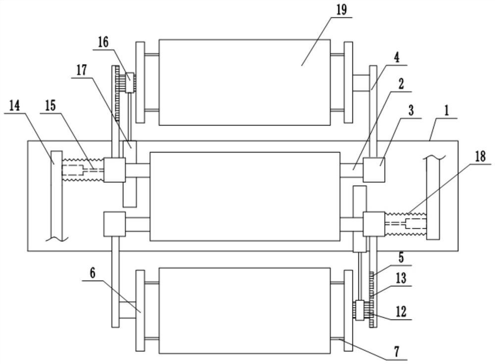
[0033] Embodiment 1 is basically as attached figure 1 As shown: the upper and unloading device for spraying includes a frame, and the upper part of the frame is fixedly connected with a spraying mechanism. The spraying mechanism includes a spraying cover with the opening facing downwards, and a spray nozzle for spraying paint on the door panel 19 is connected horizontally in the spraying cover. The spray head is arranged downwards, and the spray head communicates with a high-pressure paint box (not shown in the figure) through a conduit. There is a support platform 1 fixed on the frame under the spray head, and two parallel support seats 2 are connected horizontally on the support platform 1, and the left and right ends of the support seat 2 are fixedly connected with the connecting seat 3 to support The left and right sides of seat 2 are all provided with connecting platform 14 that is fixedly connected on the supporting platform 1, and connecting platform 14 is all fixedly c...

Embodiment 2

[0044] like image 3 , Figure 4 As shown, the only difference between this embodiment and Embodiment 1 is that in this embodiment, the adjustment assembly includes an overturning shaft 8 fixed on the overturning arm 6, and an overturning gear is affixed outside the overturning shaft 8 through a one-way bearing. 12. The overturning gear 12 is coaxially fixed with a slider 9, the slider 9 is movably connected in the support groove 5, and the end of the support arm 4 away from the support base 2 is fixedly connected with a section of overturning rack 13 that can mesh with the overturning gear 12.

[0045] During use, when the second driving cylinder 17 on the lower side pulls the turning shaft 8 to move towards the direction close to the spray head, the slider 9 slides along the support groove 5 at this time; 17 When the turning shaft 8 is pushed to move away from the nozzle, the slider 9 on the turning shaft 8 moves down along the support groove 5. When the turning gear 12 con...


PUM


Abstract

The invention relates to the field of spraying equipment and particularly discloses a loading and unloading device for spraying. The loading and unloading device for spraying comprises a supporting table; a spraying mechanism is arranged above the supporting table and comprises a nozzle capable of sliding in a length direction of the supporting table; a supporting mechanism is slidably connected to the supporting table; the sliding direction of the supporting mechanism is parallel to the sliding direction of the nozzle; two loading and unloading mechanisms which can move relative to each otherare movably connected to the supporting mechanism; relative movement directions of the two loading and unloading mechanisms are perpendicular to the sliding direction of the nozzle; and each loadingand unloading mechanism comprises an overturning assembly used for overturning a workpiece to be sprayed and a supporting assembly used for supporting the overturning assembly. The loading and unloading device for spraying solves the problems of inconvenience in double-sided paint spraying operation and poor operation continuity when a current paint spraying device sprays paints on a door plate.

Description

technical field [0001] The invention relates to the field of spraying equipment, in particular to an upper and unloading device for spraying. Background technique [0002] A door is an indispensable decorative entity used to separate limited spaces in buildings. Its function is to connect and close the entrances and exits of two or more spaces. Doors, interior doors, explosion-proof doors, blast-resistant doors, fire doors, etc. [0003] At present, solid wood doors are widely used in construction. Solid wood doors refer to the materials used to make wooden doors are natural logs or solid wood laminated wood (also known as solid wood finger-jointed wood or solid wood tooth-jointed wood) from forests. Material, planing, tenoning, drilling, high-speed milling, assembly, grinding, painting and other processes are processed. After the door panel is polished, the painting operation is usually completed by the painting production line. At present, the template is usually placed ...

Claims


Application Information

Patent Timeline
Patent Type & Authority Patents(China)
IPC IPC(8): B05B13/02
CPCB05B13/0271B05B13/0285
Inventor 唐静
Owner 重庆市佳禾家具制造有限公司
Learn More