Screw transmission unit, soil straw mixing mixer parameter adjustment method and travel method
A technology of transmission unit and mixer, which is applied in the fields of fertilizer returning to the field and agricultural machinery, can solve the problem of high cost, save time, avoid the problem of burning the machine, and improve the speed of conveying.
- Summary
- Abstract
- Description
- Claims
- Application Information
AI Technical Summary
Problems solved by technology
Method used
Image

Examples
specific Embodiment approach 1
[0046] The following is the specific implementation of the spiral transmission unit.
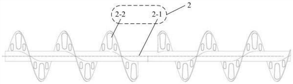
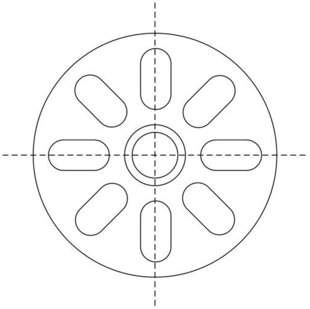
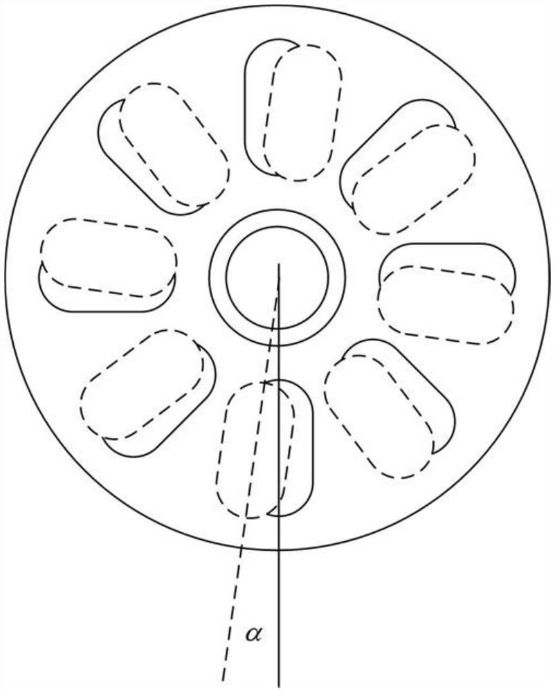
[0047] The spiral transmission unit of the present embodiment, such as figure 1 As shown, the screw transmission unit includes a second rotating shaft 2-1 and two helical blades 2-2 symmetrically distributed on the second rotating shaft 2-1. The helical directions of the two helical blades 2-2 are opposite, and the helical blades 2-2 There are also long holes evenly distributed on 2, and the schematic diagram after the spiral blade is unfolded is as follows figure 2 As shown, the number of long holes on each helical blade 2-2 is N, in figure 2 Among them, N=8, the angle between the corresponding long holes is α, and the schematic diagram of the angle between the corresponding long holes between two adjacent spiral blades 2-2 is α as shown image 3 shown.
[0048] It should be noted that, in image 3 , α≠0, however, in the actual application process, it is recommended to set α to 0, which...
specific Embodiment approach 2
[0049] The following is the specific implementation of the spiral transmission unit.
[0050] The spiral transmission unit of this embodiment, on the basis of the specific embodiment 1, is further defined as Figure 4 As shown in the soil straw mixing mixer, the soil straw mixing mixer is set in sequence from front to back as Figure 5 The shown deep rotary mixing crushed soil unit 1 and the spiral transmission unit 2 described in the specific embodiment 1; the deep rotary mixed soil crushing unit 1 includes a first rotating shaft 1-1 and uniformly distributed on the first rotating shaft 1-1 The deep rotary knife shovel 1-2 on 1; its working principle is: when the soil straw mixing mixer is advancing, the deep rotary knife shovel 1-2 in the deep rotary mixed soil unit 1 will plow the soil and simultaneously cover The straw on the soil surface is mixed with the soil; the spiral conveying unit 2 relies on the spiral blade 2-2 to transport the soil mixed with the straw to the mi...
specific Embodiment approach 3
[0051] The following is the specific implementation of the parameter adjustment method of the soil straw mixing mixer.
[0052] The parameter adjustment method of the soil straw mixing mixer in this embodiment is applicable to the soil straw mixing mixer described in Embodiment 2. The parameter adjustment method refers to a parameter adjustment method, which includes the following steps:
[0053] Step a. Estimate the maximum transmission speed V of the mixed soil in the spiral transmission unit 2 according to the soil quality and straw content;
[0054] Step b. Calculate the transmission speed of the mixed soil according to the radius r of the axial projection of the spiral blade 2-2
[0055]
[0056] Step c, according to the distance d between two adjacent spiral blades 2-2, calculate the time required for mixing soil from one spiral blade 2-2 to the other spiral blade 2-2 in two adjacent spiral blades 2-2 t
[0057]
[0058] Step d, according to the number N of long ...
PUM
 Abstract
Description
Claims
Application Information
 - R&D
- Intellectual Property
- Life Sciences
- Materials
- Tech Scout
- Unparalleled Data Quality
- Higher Quality Content
- 60% Fewer Hallucinations
Browse by: Latest US Patents, China's latest patents, Technical Efficacy Thesaurus, Application Domain, Technology Topic, Popular Technical Reports.
© 2025 PatSnap. All rights reserved.Legal|Privacy policy|Modern Slavery Act Transparency Statement|Sitemap|About US| Contact US: help@patsnap.com