Combine

A combine harvester and machine body technology, which is applied to harvesters, cutters, mechanical equipment, etc., can solve the problems of reduced work efficiency and storage capacity, and achieve the effect of increased efficiency

Active Publication Date: 2020-01-07
ISEKI & CO LTD
View PDF6 Cites 0 Cited by
  • Summary
  • Abstract
  • Description
  • Claims
  • Application Information

AI Technical Summary

Problems solved by technology

[0004] However, in the technology disclosed in Patent Document 1, there is a problem that in order to form a concave portion on the rear wall of the grain bin, the storage capacity of the grain bin is reduced and it is not possible to Grain discharge operation is performed without frequent interruption of harvesting operation, which reduces work efficiency

Method used


Image

  • Combine
  • Combine
  • Combine

Examples


Embodiment Construction

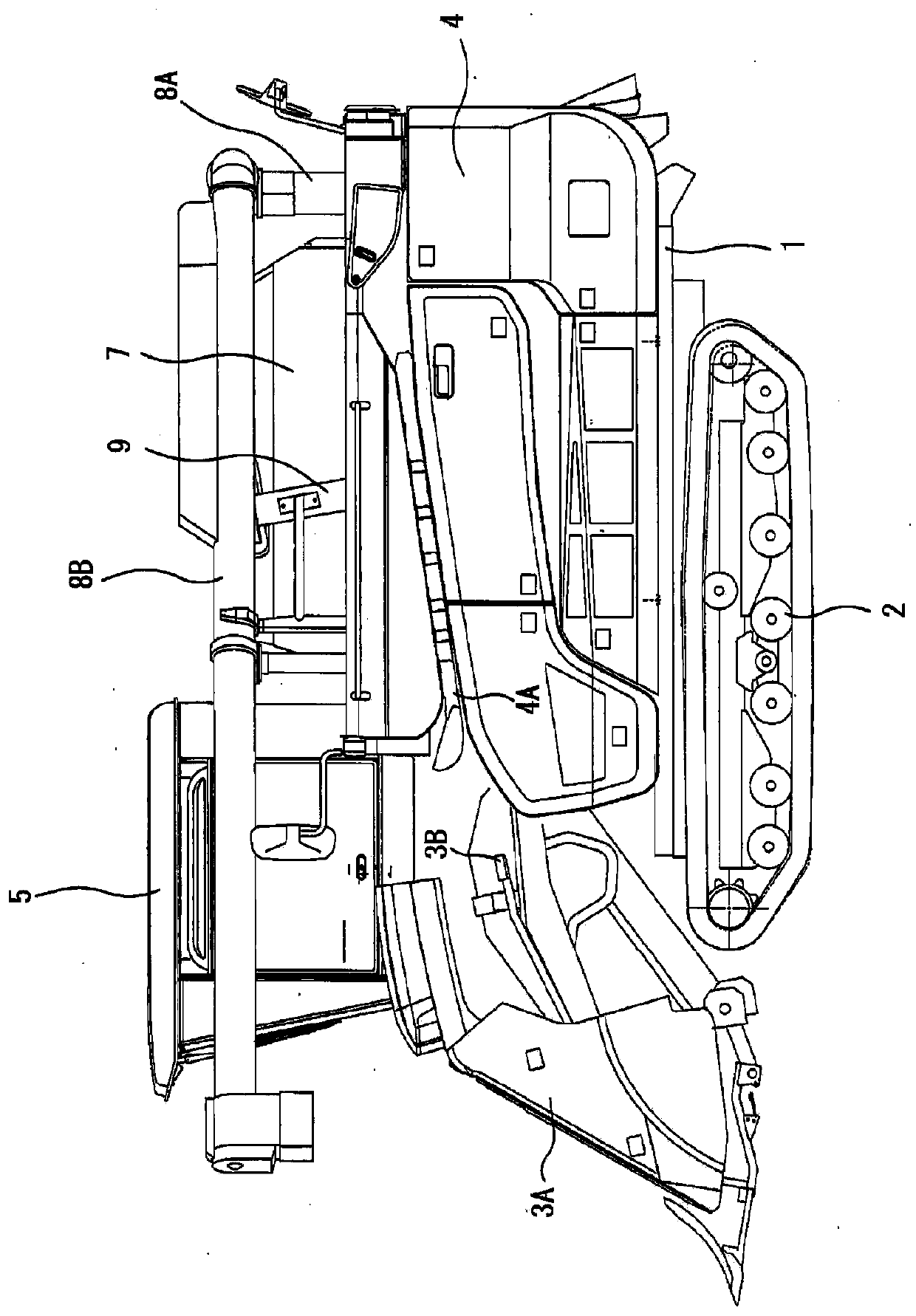
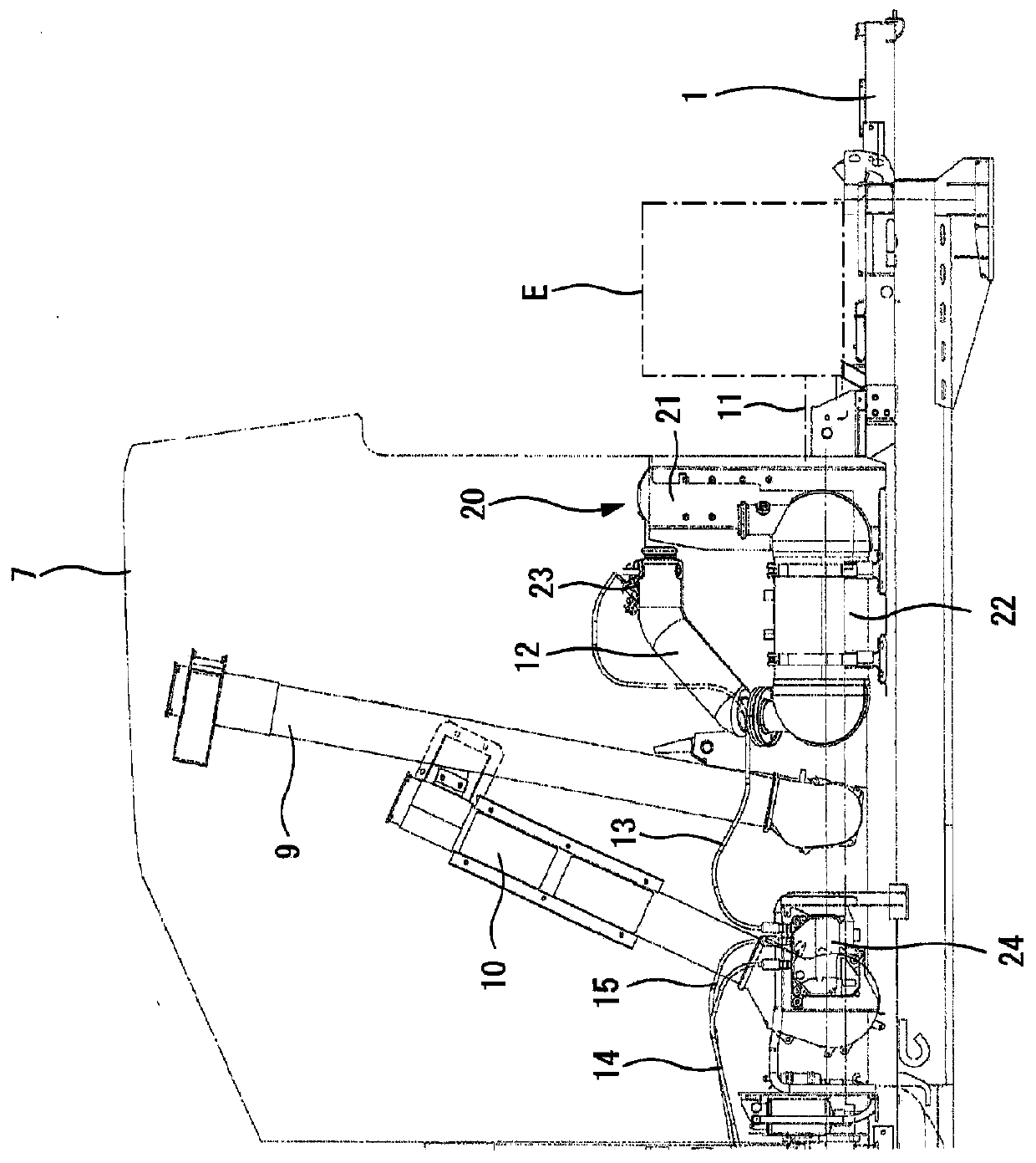
[0033] Such as figure 1 , figure 2 As shown, in the combine harvester, the lower side of the body frame 1 is provided with a traveling device 2 that travels on the soil surface and is composed of a pair of left and right crawlers. Harvesting device 3 for harvesting with rods. A threshing device 4 for threshing / screening the harvested grain stems is provided on the rear left side of the harvesting device 3, and a threshing device 4 for the operator to board is provided on the rear right side of the harvesting device 3. Part 5.

[0034] The engine room 6 equipped with the engine E is provided on the lower side of the manipulation part 5, and the grain bin 7 which stores the grains after the threshing / screening process is arranged on the rear side of the manipulation part 5. The side is provided with the discharge auger 8 which discharges a grain to the outside, and this discharge auger 8 is comprised from the trough raising part 8A extended in the up-down direction, and the h...


PUM


Abstract

The present invention provides a combine harvester capable of ensuring the storage capacity of a grain silo and easily replenishing a urea aqueous solution to a urea water tank. The combine is provided with an exhaust gas purification device (20) for purifying exhaust gas of the engine (E). The exhaust purification device (20) includes: an oxidation catalyst (21) that oxidizes unburned gas in theexhaust gas discharged from the engine (E); an SCR (22) which uses ammonia generated from urea water to reduce nitrogen oxides in the exhaust gas so as to purify the same after the exhaust gas passesthrough the oxidation catalyst (21). The combine is provided with a urea water tank (25) that stores urea water supplied to the SCR (22), the urea water tank (25) is arranged on the rear side of the rear wall of the grain silo (7) and outside the body of the valley part (8A), and a water supply port (25A) of the urea water tank (25) is arranged toward the rear of the body.

Description

technical field [0001] The present invention relates to a combine harvester with an exhaust purification device. Background technique [0002] Conventionally, the following technologies are known: in a combine harvester, there are: an oxidation catalyst that oxidizes unburned gas in the exhaust gas burned in the engine; and an SCR catalyst that oxidizes the unburned gas in the exhaust gas that passes through the oxidation catalyst Nitrogen oxides are purified, and a recess is formed on the rear wall of the grain silo for storing grains, and a urea water tank is disposed in the recess, and the urea water tank stores an aqueous urea solution supplied to the SCR catalyst. (Patent Document 1) [0003] Patent Document 1: Japanese Patent Laid-Open No. 2017-104083 [0004] However, in the technology disclosed in Patent Document 1, there is the following problem: in order to form a concave portion on the rear wall of the grain silo, the storage capacity of the grain silo is reduce...

Claims


Application Information

Patent Timeline
Patent Type & Authority Applications(China)
IPC IPC(8): A01D41/12B01D53/86
CPCA01D41/12B01D53/8625Y02A50/20Y02T10/12F01N3/0828
Inventor 上路嘉隆市丸智之上田光瑠
Owner ISEKI & CO LTD
Why Eureka
Try Eureka