An electromagnetic energy harvester

An energy harvester and electromagnetic technology, applied in the direction of electric components, electromechanical devices, electrical components, etc., can solve the problems of large energy loss, reduced output power, and limited application range, so as to increase output power, reduce friction loss, and apply wide range of effects

Active Publication Date: 2021-07-23
XIDIAN UNIV
View PDF5 Cites 1 Cited by
  • Summary
  • Abstract
  • Description
  • Claims
  • Application Information

AI Technical Summary

Problems solved by technology

[0007] In the above-mentioned energy harvester, there is collision and friction between the rotor and the cylinder wall, and the energy loss is large, which reduces the output power; moreover, the above-mentioned energy harvester can only work when it is installed vertically, and its application range is limited

Method used


Image

  • An electromagnetic energy harvester
  • An electromagnetic energy harvester
  • An electromagnetic energy harvester

Examples


Embodiment Construction

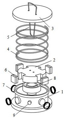
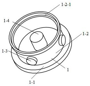
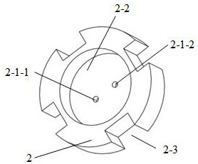
[0031] Such as figure 1 , Figure 5 As shown, an electromagnetic energy harvester at least includes a base 1, a rotor 2, a top cover 3, a spring 4, a cord 5, four magnets 6, four coils 7, a radial bearing 8, and a ferromagnetic patch 9 ; The base 1 includes a cylinder bottom 1-1, a cylinder 1-2, several cylindrical protrusions 1-3, a cylinder shaft 1-4, and a first blind hole 1-2-1; the cylinder 1- 2. perpendicular to the cylinder bottom 1-1 and coaxial with the cylinder bottom 1-1; the cylinder shaft 1-4 is cylindrical, and the cylinder shaft 1-4 is vertically and fixedly connected to the center of the base 1; The cylindrical protrusion 1-3 is fixed on the outer cylindrical surface of the cylinder 1-2, and the cylindrical protrusion 1-3 is evenly distributed on the surface of the cylinder 1-2; the first blind hole 1 -2-1 is on the surface of the cylinder 1-2 and is coaxial with the cylinder 1-2; the lower end of the spring 4 is embedded in the base 1; the upper end of the s...


PUM


Abstract

The invention belongs to the technical field of renewable energy and micro-miniature power generation, and in particular relates to a two-degree-of-freedom electromagnetic energy harvester that converts vibration and linear reciprocating motion into rotational motion. The device is characterized by at least comprising a base, a rotor, a Top cover, spring, wire rope, magnet, coil, radial bearing, ferromagnetic patch; the radial bearing is fixedly connected with the cylindrical shaft; the rotor is fixedly connected with the outer ring of the radial bearing; the two ends of the spring are respectively connected with the top cover It is fixedly connected with the base to support the top cover to move up and down; several groups of magnets are fixed on the rotor; two ferromagnetic patches are fixed on the outer cylindrical surface of the cylinder; when the external excitation acts on the top cover, the rope will drive the rotor to rotate , the magnets fixed on the rotor and the coils move relative to each other, and continuously output electric energy through the principle of electromagnetic induction; the energy harvester has the characteristics of large output power, wide operating frequency, not affected by the placement direction, and wide application range.

Description

technical field [0001] The invention belongs to the technical field of renewable energy and micro power generation, and in particular relates to an electromagnetic energy harvester which converts vibration or rectilinear reciprocating motion into rotational motion, which can convert mechanical energy in the environment into electrical energy for portable electronic equipment, air quality, etc. Low-power devices such as monitoring devices and wireless sensors are powered. Background technique [0002] In recent years, with the rapid development of microfabrication technology and the miniaturization of electronic equipment, low-power electronic devices such as wearable electronic equipment, tunnel and bridge status monitoring equipment continue to emerge. At present, these devices mainly rely on traditional batteries for power supply, but batteries have disadvantages such as large environmental pollution, need for regular replacement, and high cost. Therefore, finding a new e...

Claims


Application Information

Patent Timeline
Patent Type & Authority Patents(China)
IPC IPC(8): H02K7/18H02K7/06
CPCH02K7/06H02K7/1807
Inventor 樊康旗蔡美玲谭钦雪朱应敏
Owner XIDIAN UNIV
Why Eureka
Try Eureka