
Armored fiber jumper laser armor stripping device

A laser and fiber jumper technology, applied in light guides, optics, instruments, etc., can solve the problems of irregular armor cutting, slow operation speed, and affecting production efficiency, and achieve uniform lengths, improve work efficiency, and facilitate standardization.

Active Publication Date: 2020-01-03
SICHUAN TIANYI COMHEART TELECOM
View PDF13 Cites 0 Cited by
  • Summary
  • Abstract
  • Description
  • Claims
  • Application Information

AI Technical Summary

Problems solved by technology

Manual operation is very slow, seriously affecting production efficiency
And when cutting, it is easy to cut the armor on the surface irregularly, causing the tight-packed optical fiber inside to fail to shrink normally, and it is easy to scratch the tight-packed optical fiber, resulting in damage to the optical fiber and unqualified optical parameters, which affects the one-time pass rate of the product and the stability of the product. sex
Or manually pull out the steel armor and cut it with scissors, and then return the steel armor, but the degree of tightness of the steel armor in the armored optical fiber is different, some steel armor is easy to pull out, some steel armor cannot be pulled out, and some can be pulled out The steel armor may not be able to return to its original position, so the manual method of cutting with scissors is inefficient and unstable, which seriously affects the production plan

Method used


Image

  • Armored fiber jumper laser armor stripping device
  • Armored fiber jumper laser armor stripping device
  • Armored fiber jumper laser armor stripping device

Examples


Embodiment Construction

[0030] The present invention will be further described below in conjunction with the accompanying drawings, but the protection scope of the present invention is not limited to the following description.

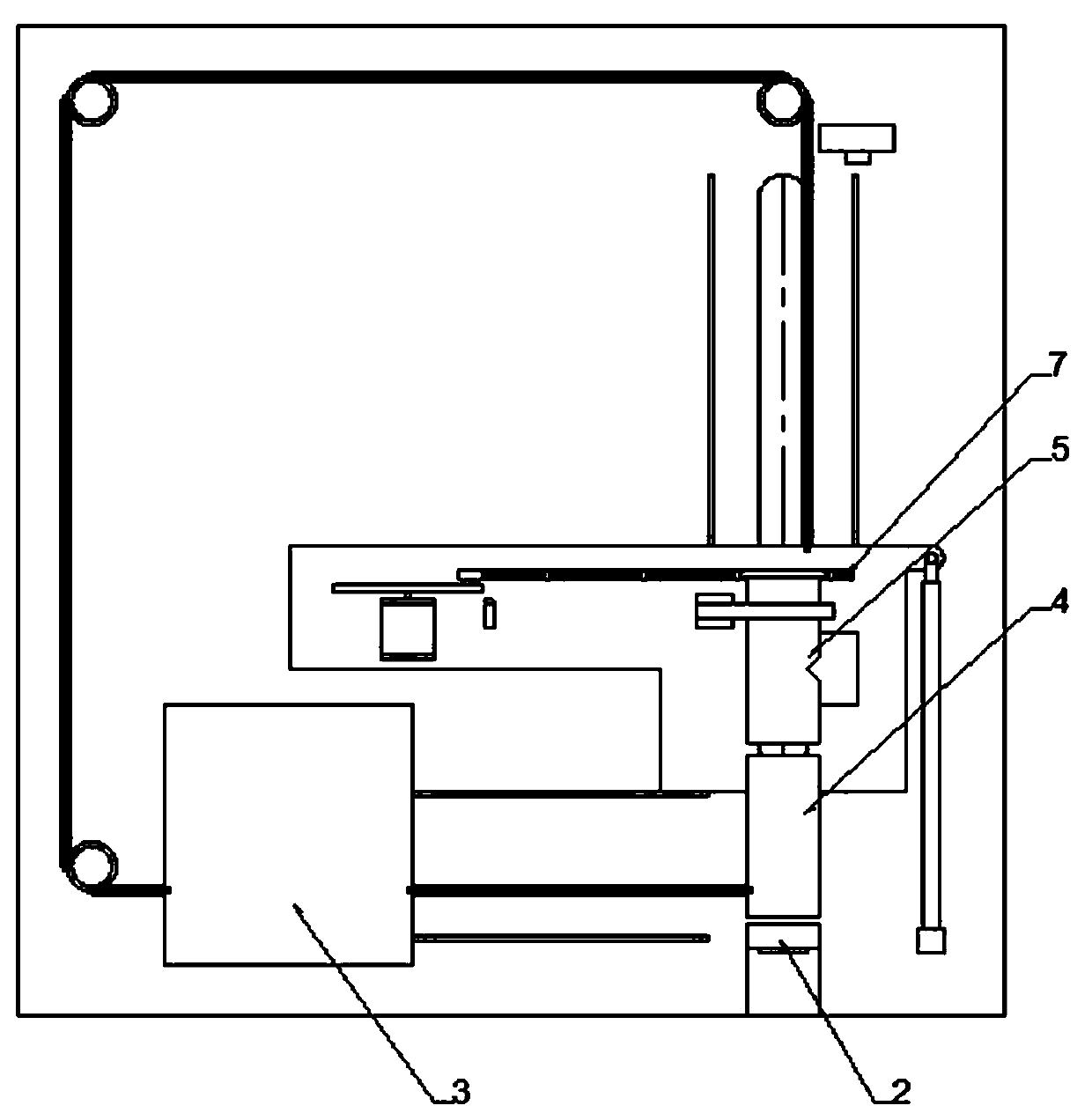
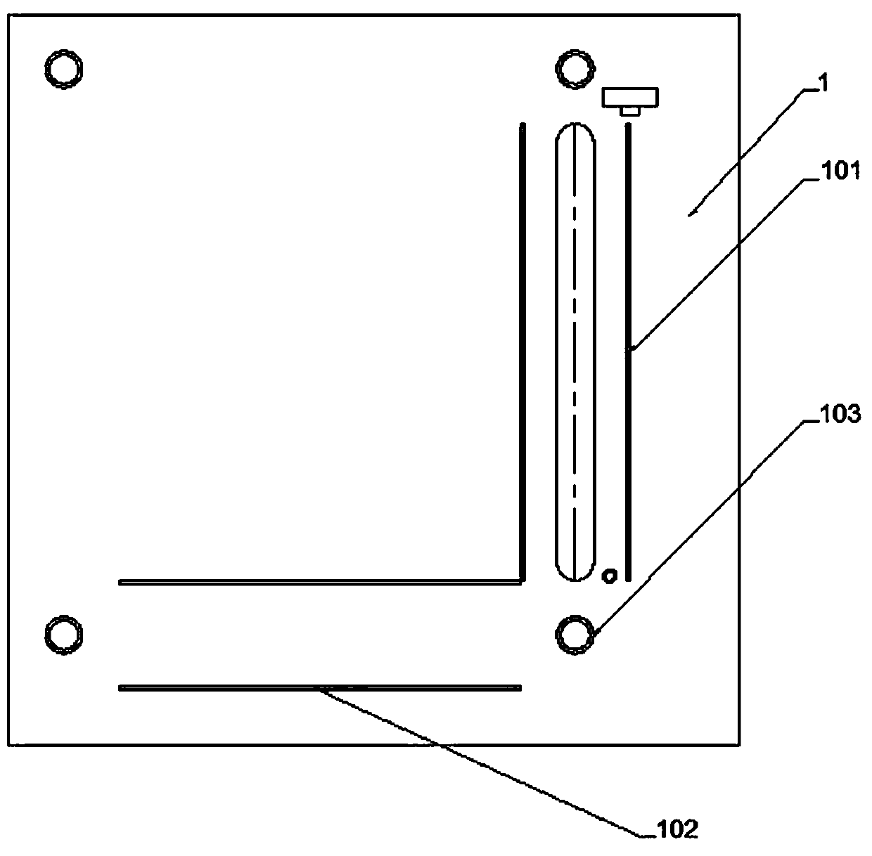
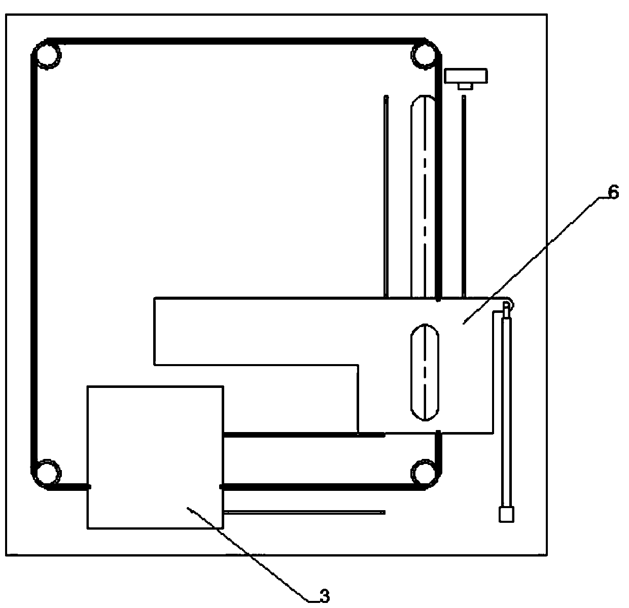
[0031] Such as figure 1 As shown, an armored fiber jumper laser armor stripper for armored fiber jumpers, including a base 1, a fixing fixture 2, a sheath cutter 4, an aramid cutter 3, a steel armor cutter 5 and a slide plate 6 ; The base 1 is provided with a longitudinal slide rail 101 and a transverse slide rail 102, and the outer skin shearer 4 and the steel armor cutter 5 are all arranged on the slide plate 6, so that the outer skin shearer 4 and the steel armor cutter 5 The distance is fixed, which can ensure that the length of the optical fiber after each peeling is consistent. The bottom of the slide plate 6 is provided with a groove that cooperates with the longitudinal slide rail 101 and is connected with the longitudinal slide rail 101. The bottom of the aramid cutt...


PUM


Abstract

The invention relates to an armored fiber jumper laser armor stripping device. The device comprises a base (1), a stationary fixture (2), an outer sheath shearer (4), an aramid fiber shearer(3), a steel armor cutter (5) and a sliding plate (6); a longitudinal sliding rail (101) and a transverse sliding rail (102) are arranged on the base (1); the outer sheath shearer (4) and the steel armor cutter(5) are arranged on the sliding plate (6), a groove matched with the longitudinal sliding rail (101) is arranged at the bottom of the sliding plate (6), and the bottom of the sliding plate is connected with the longitudinal sliding rail (101); a groove matched with the transverse sliding rail (102) is arranged at the bottom of the aramid fiber shearer (3) and the bottom of the aramid fiber shearer is connected with the transverse sliding rail (102); the stationary fixture (2) is arranged on the base (1), and optical fiber through holes for the penetration of the optical fiber are arranged onthe stationary fixture (2) and the outer sheath shearer (4). After shearing the outer sheath and the aramid, the steel armor cutter (5) cuts the steel armor in a rotary manner through the principle that the laser cannot cut the optical fiber.

Description

technical field [0001] The invention relates to the field of optical fiber processing tooling, in particular to an armored fiber jumper laser armor stripper. Background technique [0002] When the armored jumper is operated in the armor stripping process, the currently used armor stripper is manually operated. After the armored optical cable is stripped and the aramid yarn is cut, it is put into the hole of the armor stripper, and the steel armor is manually put into the hole. The armor stripper props the handle and cuts it off when it is turned to a suitable length. Manual operation is very slow, seriously affecting production efficiency. And when cutting, it is easy to cut the armor on the surface irregularly, causing the tight-packed optical fiber inside to fail to shrink normally, and it is easy to scratch the tight-packed optical fiber, resulting in damage to the optical fiber and unqualified optical parameters, which affects the one-time pass rate of the product and t...

Claims


Application Information

Patent Timeline
Patent Type & Authority Applications(China)
IPC IPC(8): G02B6/245
CPCG02B6/245
Inventor 黄成刘学坤范建川廖静
Owner SICHUAN TIANYI COMHEART TELECOM
Learn More