Steel framing fixtures for civil engineering

A technology of civil engineering and fixing devices, which is applied in the processing of building materials, construction, building construction, etc., and can solve the problems of inconvenient operation of the supporting frame and the lack of wide applicability of the device

Active Publication Date: 2021-03-02
ZHENGZHOU INST OF TECH
View PDF6 Cites 0 Cited by
  • Summary
  • Abstract
  • Description
  • Claims
  • Application Information

AI Technical Summary

Problems solved by technology

[0010] In view of the above situation, in order to overcome the defects of the prior art, the present invention provides a steel frame fixing device for civil engineering, which effectively solves the problem that the existing device does not have wide applicability and is inconvenient to operate with a fixed support frame

Method used


Image

  • Steel framing fixtures for civil engineering
  • Steel framing fixtures for civil engineering
  • Steel framing fixtures for civil engineering

Examples


Embodiment 1

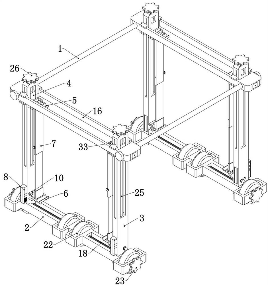
[0041] Embodiment 1, the present invention is a steel frame fixing device for civil engineering, which is characterized in that it includes two support frames, and two sliding shafts 1 are slidably connected between the two support frames, and the two support frames have exactly the same structure, All of them can slide along the sliding shaft 1;

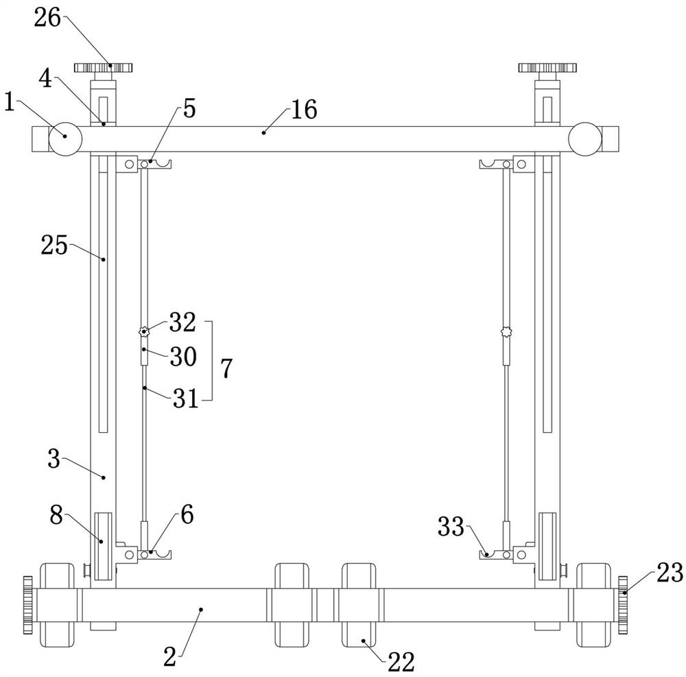
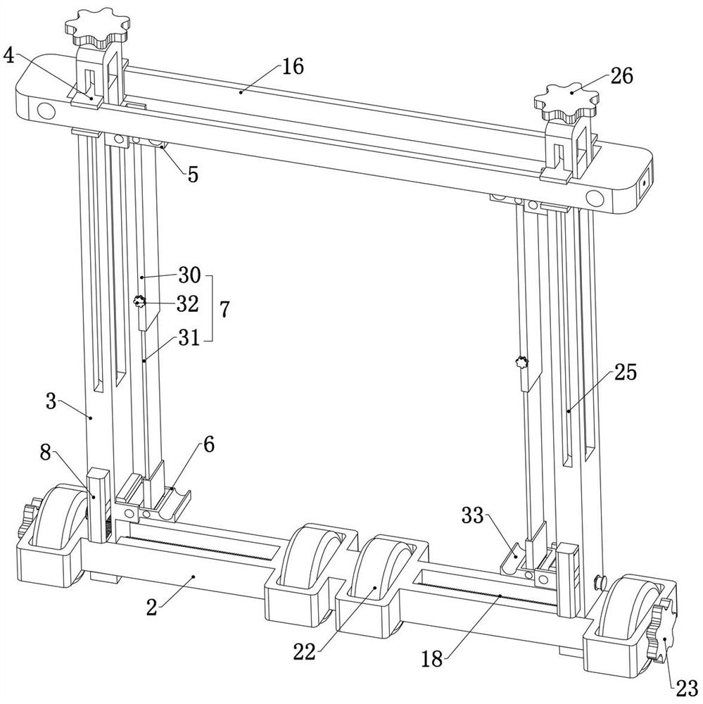
[0042] The supporting frame includes a walking beam 2. The walking beam 2 is the fixed foundation of the subsequent structure of the supporting frame. It is located below the main reinforcement of the beam and column when in use. The walking beam 2 is slidingly connected with two vertical beams 3 left and right. The two vertical beams 3 slide up and down and are connected with a movable base 4. Specifically, refer to figure 1, the walking beam 2 is provided with two vertical beams 3 chute, the lower ends of the two vertical beams 3 are slidingly connected in the two vertical beams 3 chute respectively, and the two vertical beams 3 a...

Embodiment 2

[0046] Embodiment two, on the basis of embodiment one, refer to Figure 11 One end of the contact connection between the locked slider 15 and the sliding shaft 1 is fixedly connected with a rubber pad 17, and the rubber pad 17 is set so that when the locked slider 15 is pressed on the sliding shaft 1, the locked slider 15 There is greater friction between the sliding shaft 1 and the sliding shaft 1, thereby facilitating the fixing of the sliding shaft 1.

Embodiment 3

[0047] Embodiment three, on the basis of embodiment one, each of the supporting frames includes a double-ended screw 18, and the double-ended screw 18 is rotatably connected to the walking beam 2, and the double-ended screw 18 passes through the lower ends of the two vertical beams 3 and the two vertical beams 3 are threaded. Specifically, the lower ends of the two vertical beams 3 are provided with threaded holes for the vertical beams 3. The double-ended Both ends of the screw 18 pass through the threaded holes of the two vertical beams 3 respectively, and the rotation of the double-ended screw 18 can drive the two vertical beams 3 to approach or move away from each other.


PUM


Abstract

The invention relates to a steel frame fixing device for civil engineering, which effectively solves the problem that the existing device does not have wide applicability and is inconvenient to use a fixed support frame; the technical solution is to include two support frames, two support frames There are two sliding shafts slidingly connected between the frames; the supporting frame includes a walking beam, and there are two vertical beams on the walking beam, and there are movable bases on the two vertical beams, upper supporting plates on the two movable bases, and two walking beams. There are lower supporting plates at the lower end of the beam, and telescopic rods at the lower ends of the two upper supporting plates. There are driving wedges in the boards, pressure blocks are installed on one side of the two pressing plates, and driven wedges are installed on the other side of the two pressure blocks, and the two driven wedges are connected to the corresponding vertical beams through springs ; The structure of the present invention is simple, easy to operate, and can effectively assist workers to support the main reinforcement.

Description

technical field [0001] The invention relates to the technical field of civil engineering auxiliary tools, in particular to a steel frame fixing device for civil engineering. Background technique [0002] In civil engineering construction, when making steel bars for beams and columns, the main bars and stirrups are usually combined to form a steel bar frame for beams and columns. Specifically, the four main bars are placed at the four corners of a rectangle, and then the prefabricated stirrups are placed The reinforcements are fixed around the four main reinforcements by steel wires to form a rectangle, and then the stirrups are tied at intervals according to the construction drawings, and finally the main body of the beams and columns can be obtained, and then the formwork is bound and poured. [0003] In the process of binding stirrups, because the steel bars used for the main reinforcement are usually standard rebars of various grades, and the standard rebars are all 12 me...

Claims


Application Information

Patent Timeline
Patent Type & Authority Patents(China)
IPC IPC(8): E04G21/12
CPCE04G21/12
Inventor 王代王勇智王蕾汪菁蒋辉刘喜王倩倩周帅
Owner ZHENGZHOU INST OF TECH
Why Eureka
Try Eureka