Hydraulic excavator control system and method
A technology of hydraulic excavator and control method, which is applied in the direction of earth mover/shovel, construction, etc., can solve the problems of reduced engine work efficiency and black smoke, so as to reduce fuel consumption, reduce idle speed, and improve work efficiency Effect
- Summary
- Abstract
- Description
- Claims
- Application Information
AI Technical Summary
Problems solved by technology
Method used
Image
Examples
Embodiment 1
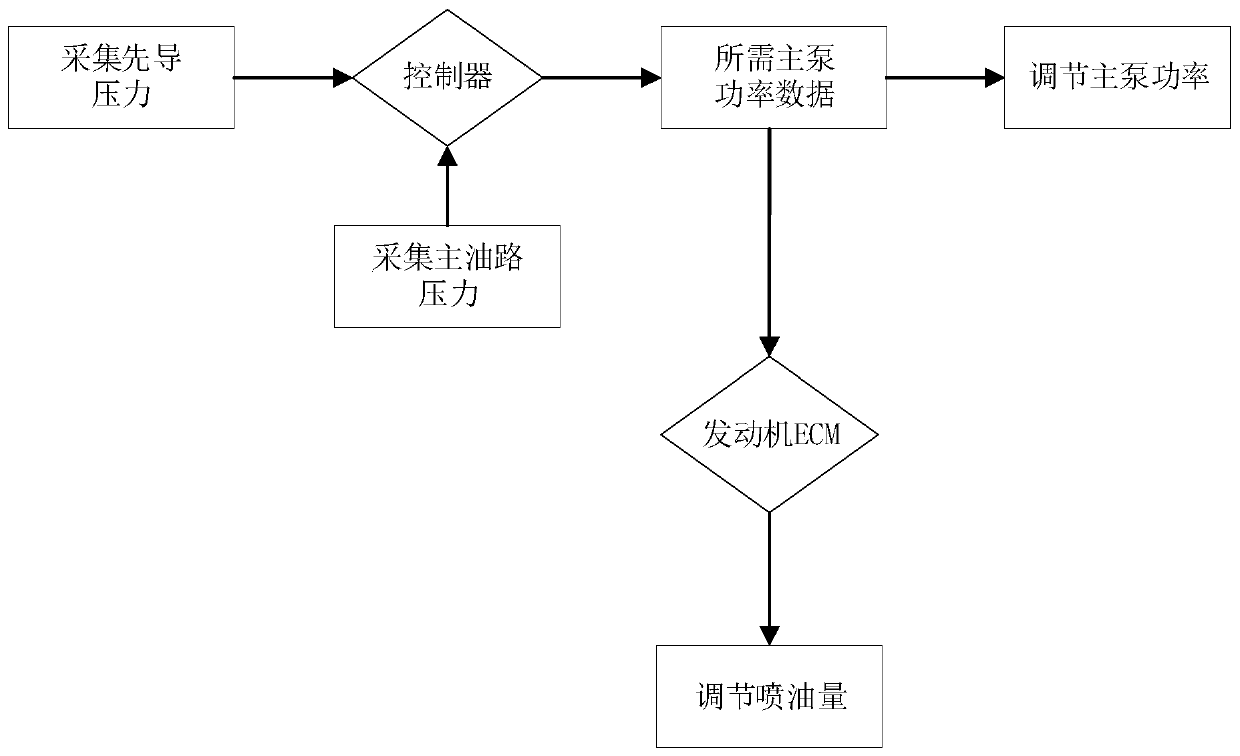
[0024] Such as figure 1 Shown is a flow chart of a hydraulic excavator control method provided by an embodiment of the present invention, which mainly includes the following steps:
[0025] Collect the main oil circuit pressure value of the hydraulic excavator and the pilot pressure values corresponding to the current action of the hydraulic excavator, and the controller The pilot pressure value of each channel obtains the required main pump power, and sends the required main pump power to the engine ECM; the controller can adjust the main pump power according to the required main pump power; the engine ECM can adjust the main pump power according to the described The required main pump power adjusts the fuel injection quantity of the engine, and the start time of the engine ECM to adjust the fuel injection quantity of the engine is earlier than the start time of the controller to adjust the main pump power.
[0026] The start time of the engine ECM to adjust the fuel injec...
Embodiment 2
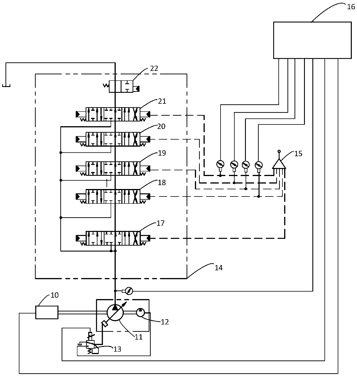
[0029] Such as figure 2 As shown, it is a hydraulic principle diagram of a hydraulic excavator control system provided by the embodiment of the present invention, including: engine 10, main pump 11, pilot pump 12, electromagnetic proportional valve 13, main valve 14, hydraulic pilot handle 15, control device 16, a first pressure acquisition unit and a second pressure acquisition unit;
[0030] The engine 10 is connected with the main pump 11 and the pilot pump 12, and is used to provide power for the main pump 11 and the pilot pump 12;
[0031] The main valve 14 includes a walking spool 17, a rotary spool 18, a boom spool 19, a bucket spool 20 and a stick spool 21. After the outlet of the main pump 11 is connected to the inlet of the main valve 14 through a pipeline, It is connected with the travel spool 17, the rotary spool 18, the boom spool 19, the bucket spool 20 and the arm spool 21 in turn, supplying oil for each action spool to form the main oil circuit; the oil retur...
PUM
 Abstract
Description
Claims
Application Information
 - Generate Ideas
- Intellectual Property
- Life Sciences
- Materials
- Tech Scout
- Unparalleled Data Quality
- Higher Quality Content
- 60% Fewer Hallucinations
Browse by: Latest US Patents, China's latest patents, Technical Efficacy Thesaurus, Application Domain, Technology Topic, Popular Technical Reports.
© 2025 PatSnap. All rights reserved.Legal|Privacy policy|Modern Slavery Act Transparency Statement|Sitemap|About US| Contact US: help@patsnap.com


