
Long-distance insulated power transmission bus

A long-distance, busbar technology, applied in the direction of transportation and packaging, containers to prevent mechanical damage, clamping devices, etc., can solve the problems of power transmission busbar surface damage, vehicle bumps, insulation performance effects, etc., to achieve protection integrity, prevent The effect of skin abrasion and simple structure

Active Publication Date: 2020-01-03
江苏中顺电气有限公司
View PDF7 Cites 1 Cited by
  • Summary
  • Abstract
  • Description
  • Claims
  • Application Information

AI Technical Summary

Problems solved by technology

In the power system, the power transmission bus connects the various current-carrying branch circuits in the power distribution device, and plays the role of collecting, distributing and transmitting electric energy. Therefore, the power transmission bus is used in large quantities in power distribution equipment. When transporting a large number of power transmission buses to various power distribution equipment, they are often directly put into transport vehicles without protective equipment and transported to the destination, but there will be bumps during the driving of the vehicle, and the resulting bumps will make the power transmission bus The friction between the skin and the compartment will cause damage to the skin of the transmission bus and affect its insulation performance. Therefore, we propose a long-distance insulated transmission bus to solve the above problems

Method used


Image

  • Long-distance insulated power transmission bus
  • Long-distance insulated power transmission bus

Examples


Embodiment Construction

[0017] The following will clearly and completely describe the technical solutions in the embodiments of the present invention with reference to the accompanying drawings in the embodiments of the present invention. Obviously, the described embodiments are only some, not all, embodiments of the present invention.

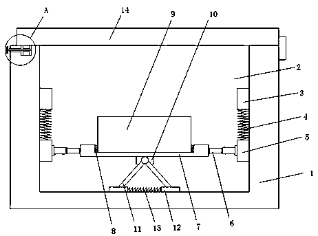
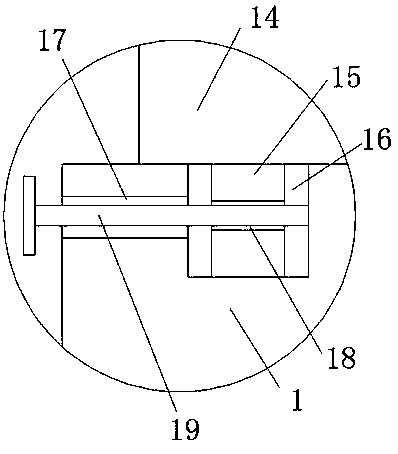
[0018] refer to Figure 1-2 , a long-distance insulated power transmission bus, comprising a protective box 1, the top of the protective box 1 is provided with a protective groove 2, the inner walls of both sides of the protective groove 2 are slidingly connected with a positioning plate 3, and the bottom of the positioning plate 3 is fixedly connected with a pull Stretching spring 4, the bottom of the stretching spring 4 is fixedly connected with a moving plate 5, one side of the moving plate 5 is slidingly connected with the side wall of the protective groove 2, and the sides of the two moving plates 5 close to each other are fixedly installed with buffer hydraulic ...


PUM


Abstract

The invention discloses a long-distance insulated power transmission bus which includes a protection box. A protection groove is formed in the top of the protection box, positioning plates are slidably connected to the inner walls of the two sides of the protection grooves, and the bottoms of the positioning plates are fixedly connected with extension springs; moving plates are fixedly connected to the bottoms of the extension springs, one sides of the moving plates are slidably connected to the side wall of the protection groove, buffer hydraulic rods are fixedly installed on the sides, closeto each other, of the two moving plates, and a same placing plate is fixedly connected to the sides, close to each other, of the two buffer hydraulic rods; and a placing groove is formed in the top of the placing plate, and cushion pads are fixedly connected to the inner walls of the two sides of the placing groove. The long-distance insulated power transmission bus is simple in structure, buffersprings, the extension springs and the buffer hydraulic rods are utilized to carry out buffering protection on vibration generated during the power transmission bus body transportation, the skin of apower transmission bus body is prevented from abrasion, and the integrity of the power transmission bus body is protected.

Description

technical field [0001] The invention relates to the technical field of electric equipment, in particular to a long-distance insulated power transmission bus. Background technique [0002] Power equipment mainly includes power generation equipment and power supply equipment. Power generation equipment is mainly power plant boilers, steam turbines, gas turbines, water turbines, generators, transformers, etc. Power supply equipment is mainly transmission lines of various voltage levels, transformers, contactors, etc. device etc. [0003] The invention with the notification number CN204361629U discloses an ultra-high voltage long-distance insulated power transmission busbar in the field of power transmission, including a transmission shell connecting two outlet bushings, conductors are arranged in the outlet bushing and the transmission shell, and the two ends of the transmission shell are Both ends are equipped with insulating and sealing structures. The insulating and sealing...

Claims


Application Information

Patent Timeline
Patent Type & Authority Applications(China)
IPC IPC(8): B65D45/02B65D25/10B65D81/07
CPCB65D25/10B65D45/02B65D81/07
Inventor 刘洋
Owner 江苏中顺电气有限公司
Learn More