Butyl rubber sheet cutting machine

A butyl rubber and cutting machine technology, applied in metal processing and other directions, can solve problems such as waste and inconvenience in use, and achieve the effects of convenient use, improved production efficiency and simple structure

Inactive Publication Date: 2020-01-03
重庆宝光车用材料有限公司
View PDF0 Cites 1 Cited by
  • Summary
  • Abstract
  • Description
  • Claims
  • Application Information

AI Technical Summary

Problems solved by technology

However, there are some defects in the existing cutting machine in use. For example, it is wasteful to cut the smaller butyl rubber sheet with an electric cutting machine, and it is necessary to use a manual cutting machine, while the existing manual cutting When the machine is in use, it cannot automatically pour the cut butyl rubber sheet into the barrel. It is necessary to manually remove the cut butyl rubber sheet to avoid affecting the subsequent cutting of the butyl rubber sheet. Therefore, inconvenient to use

Method used


Image

  • Butyl rubber sheet cutting machine
  • Butyl rubber sheet cutting machine
  • Butyl rubber sheet cutting machine

Examples


Embodiment 1

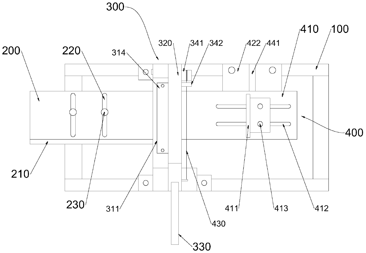
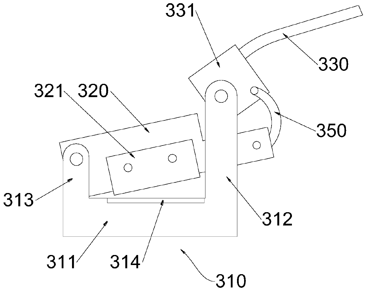
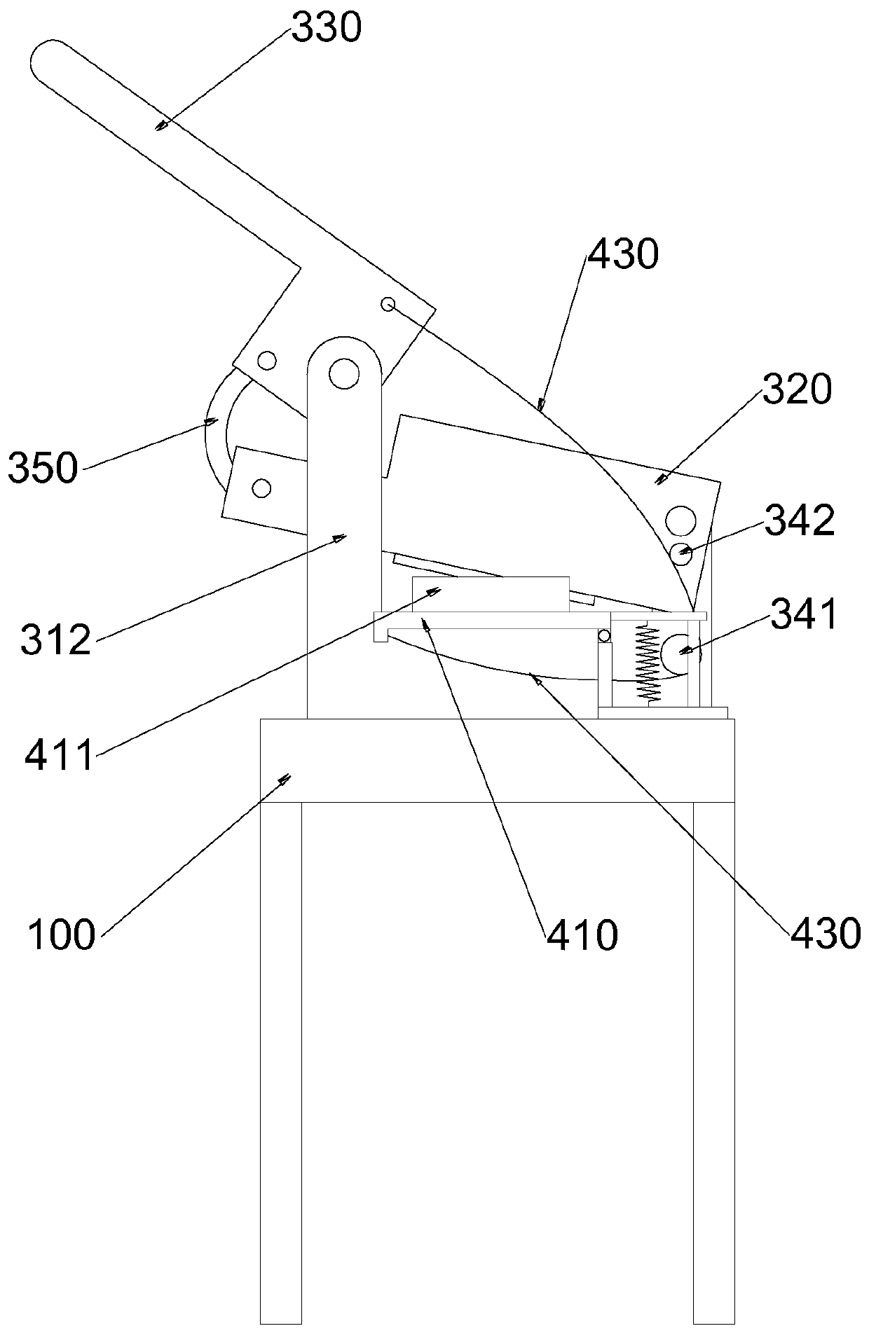
[0034] Such as figure 1In the shown first embodiment of the butyl rubber sheet cutting machine of the present invention, the butyl rubber sheet cutting machine includes a workbench 100 on which a feeding platform 200, a cutting mechanism 300 and an inverted The material mechanism 400, the cutting mechanism 300 includes a fixed knife bracket 310 and a moving knife bracket 320, the fixed knife bracket 310 includes a horizontal base 311 and a support arm 312 connected in an L-shaped structure, and one end of the moving knife bracket 320 is connected to the horizontal base 311 The hinged part 313 of the end is hinged, and the top of the support arm 312 is connected with an operating rod 330, and the operating rod 330 is connected with the other end of the movable knife bracket 320; There is a movable blade 321 on the top, and the rear side of the fixed blade 314 is staggered with the movable blade 321; the feeding platform 200 is connected to the front side of the fixed blade 314,...

Embodiment 2

[0047] The connection relationship and working principle of each component in this embodiment are the same as those in Embodiment 1, the difference is that, as Figure 5 As shown, the top of the support arm 312 in this embodiment is provided with a large fan-shaped tooth 360, and one end of the operating lever 330 is provided with a small fan-shaped tooth 370, and the large fan-shaped tooth 360 meshes with the small fan-shaped tooth 370; A central shaft is arranged and fixed, and the end of the movable knife bracket 320 away from the hinge portion 313 is movably connected with the central shaft. The large fan-shaped teeth 360 and the small fan-shaped teeth 370 are meshed for transmission, which can rotate flexibly, and can make the operating rod 330 produce the effect of decelerating and increasing force on the moving knife bracket 320, thereby enhancing the cutting ability of the cutting mechanism 300 and improving the service life.


PUM


Abstract

The invention relates to the field of plastic product producing machining, and particularly discloses a butyl rubber sheet cutting machine. The butyl rubber sheet cutting machine comprises a worktable, and a feeding platform, a cutting mechanism and a pouring mechanism are sequentially arranged on the worktable. The pouring mechanism comprises a movable plate, a mounting part, a rigid traction mechanism and a reset mechanism. The two ends of the rigid traction mechanism are connected with an operation rod and the bottom of the movable plate correspondingly, when the operation rod is downwardsrotated to drive a movable knife holder to cut a butyl rubber sheet, the rigid traction mechanism is used for adjusting the movable plate to downwards rotate and incline along the horizontal plane, and the reset mechanism provides resilience force when the movable plate is in the rotating inclining state. According to the butyl rubber sheet cutting machine, after the butyl rubber sheet is cut, thebutyl rubber sheet can conveniently fall in a material cylinder through the rotating movable plate, the operation rod of the cutting mechanism is held by the hand for up and down force exertion, a movable cover plate is rotated, and the cut butyl rubber sheet can be poured to the material cylinder to be reset.

Description

technical field [0001] The invention relates to the field of production and processing of plastic products, in particular to a butyl rubber sheet cutting machine. Background technique [0002] Butyl rubber sheet is a copolymer of isobutylene and isoprene, which has been widely used in various fields. At present, the cutting of butyl rubber sheet is generally operated manually. First, the whole piece of butyl rubber sheet is positioned, then the material is fed and cut manually, and then the size is measured manually, and the starting point of cutting is marked. Finally, the material is manually supported and cut according to the mark. [0003] The cutting machine uses the moving upper blade and the fixed lower blade, and adopts a reasonable blade gap to apply shear force to the butyl rubber sheets of various thicknesses, so that the butyl rubber sheets are broken and separated according to the required size. However, there are some defects in the existing cutting machine in...

Claims


Application Information

Patent Timeline
Patent Type & Authority Applications(China)
IPC IPC(8): B26D1/30B26D7/32
CPCB26D1/30B26D7/32
Inventor 代治军周建朱剑孙冰
Owner 重庆宝光车用材料有限公司
Why Eureka
Try Eureka