Automatic ditching device for vegetable greenhouses

A vegetable greenhouse, automatic technology, applied in the direction of excavation/covering trenches, applications, planting methods, etc., can solve the problems of impact management, uneven row spacing, uneven distribution of vegetable seeds, etc., to save labor and improve work efficiency. Effect

Inactive Publication Date: 2020-01-03
王则敏
View PDF0 Cites 10 Cited by
  • Summary
  • Abstract
  • Description
  • Claims
  • Application Information

AI Technical Summary

Problems solved by technology

[0003] When growing vegetables in greenhouses, many farmers directly sprinkle the seeds in the soil or spread the seeds in a row by hand, resulting in uneven distribution of vegetable seeds after germination and uneven row spacing, which affects later management

Method used


Image

  • Automatic ditching device for vegetable greenhouses
  • Automatic ditching device for vegetable greenhouses
  • Automatic ditching device for vegetable greenhouses

Examples


Embodiment 1

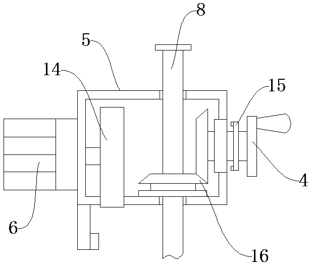
[0027] Such as Figure 1-Figure 4 As shown, an automatic ditching device for vegetable greenhouses comprises a transverse guide rail 1 and a longitudinal guide rail 9, one end of the transverse guide rail 1 is provided with a fixing ring 7, the fixing ring 7 is welded together with the transverse guide rail 1, and the other end of the transverse guide rail 1 is provided with a There are hydraulic adjustment rods 3, and limit holes 2 are processed at equal intervals on the side of the transverse guide rail 1, and limit pins 13 are arranged in the limit holes 2. A scale 11 is arranged on the upper surface of the transverse guide rail 1, and rollers 12 are arranged inside the transverse guide rail 1. The roller 12 is slidably connected inside the transverse guide rail 1, the side of the roller 12 is provided with a longitudinal guide rail 9, the upper surface of the longitudinal guide rail 9 is provided with a rack 10, the longitudinal guide rail 9 is provided with a moving seat 5...

Embodiment 2

[0029] The difference between this embodiment and Embodiment 1 is:

[0030] In this embodiment, the rack 10 is fixed on the longitudinal guide rail 9 by screws, the rack 10 meshes with the moving gear 14, and the moving gear 14 is fixed on the rotating shaft of the moving motor 6 through a key connection.

[0031] Specifically, such setting can drive the ditch opener 17 to carry out the ditching operation through the mobile motor 6, saving manpower.

[0032] The working principle of the present invention is: before use, control the hydraulic adjustment rod 3 to elongate to make the horizontal guide rail 1 rotate down to the horizontal direction, ensure that the horizontal guide rail 1 is parallel to the ground, adjust the position of the longitudinal guide rail 9 through the roller 12 and fix it with the limit pin 13 , then turn the depth adjustment handwheel 4 to make the opener 17 drop to the specified depth, use the locking plate 15 to lock the depth adjustment handwheel 4 ...


PUM


Abstract

The invention discloses an automatic ditching device for vegetable greenhouses, which comprises a transverse guide rail and a longitudinal guide rail; one end of the transverse guide rail is providedwith a fixing ring; the fixing ring and the transverse guide rail are welded together, and a hydraulic adjusting rod is arranged at the upper end of the other end of the transverse guide rail; limiting holes are machined in the lateral surface of the transverse guide rail at equal intervals, and limiting pins are arranged in the limiting holes; a scale is arranged on the upper surface of the transverse guide rail, and a roller is arranged inside the transverse guide rail; the roller is slidably connected inside the transverse guide rail, and the longitudinal guide rail is arranged on the sidesurface of the roller; a rack is arranged on the upper surface of the longitudinal guide rail, and a moving seat is arranged inside the longitudinal guide rail. The retractable mechanical scraper hasthe advantages that when not in use, the retractable mechanical scraper can be retracted upwards so that the ground space of a greenhouse is not used; automatic ditching can be provided, so that laboris saved; ditching distance and depth can be adjusted, so that different crops can be conveniently planted, and the operation efficiency is improved.

Description

technical field [0001] The invention relates to the technical field of agricultural equipment, in particular to an automatic ditching device for vegetable greenhouses. Background technique [0002] Along with the generation of high molecular polymer-polyvinyl chloride, polyethylene, plastic film is widely used in agriculture. In the early 1950s, Japan, European and American countries successfully applied greenhouse films to cover hotbeds, and then covered small sheds and greenhouses with good results. my country introduced polyvinyl chloride agricultural film in the autumn of 1955. It was first used to cover vegetables in small sheds in Beijing, and achieved the effect of early maturity and increased production. The greenhouse was originally a special equipment for vegetable production. With the development of production, the application of greenhouses has become more and more extensive. At present, greenhouses have been used for potted flower and cut flower cultivation; f...

Claims


Application Information

Patent Timeline
IPC IPC(8): A01C5/06
CPCA01C5/062
Inventor 王则敏
Owner 王则敏
Why Eureka
Try Eureka