
DC boost conversion circuit and device

A DC step-up and conversion circuit technology, which is applied in the direction of DC power supply parallel operation, DC power input conversion to DC power output, output power conversion device, etc., can solve the problems of high cost and large volume, and achieve volume reduction and cost, effect of achieving power transfer, boosting efficiency

Pending Publication Date: 2019-12-31
GLOBAL ENERGY INTERCONNECTION RES INST CO LTD +1
View PDF0 Cites 1 Cited by
  • Summary
  • Abstract
  • Description
  • Claims
  • Application Information

AI Technical Summary

Problems solved by technology

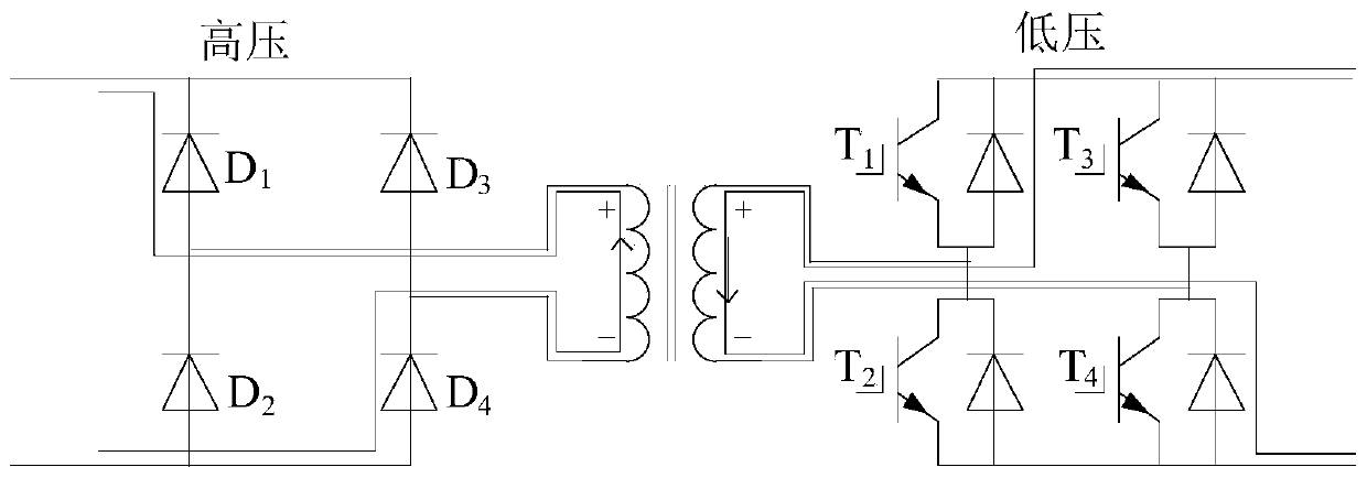
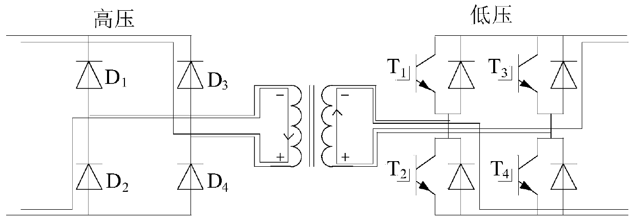
[0004] In view of this, the embodiment of the present invention provides a DC boost conversion circuit and device to solve the technical problems of high cost and large volume of the DC boost circuit in the prior art

Method used


Image

  • DC boost conversion circuit and device
  • DC boost conversion circuit and device
  • DC boost conversion circuit and device

Examples


Embodiment Construction

[0023] The technical solutions of the present invention will be clearly and completely described below in conjunction with the accompanying drawings. Apparently, the described embodiments are some of the embodiments of the present invention, but not all of them. Based on the embodiments of the present invention, all other embodiments obtained by persons of ordinary skill in the art without making creative efforts belong to the protection scope of the present invention.

[0024] In the description of the present invention, it should be noted that the terms "center", "upper", "lower", "left", "right", "vertical", "horizontal", "inner", "outer" etc. The indicated orientation or positional relationship is based on the orientation or positional relationship shown in the drawings, and is only for the convenience of describing the present invention and simplifying the description, rather than indicating or implying that the referred device or element must have a specific orientation, ...


PUM


Abstract

The invention discloses a DC boost conversion circuit and device. The circuit comprises a full control circuit, a transformer and an uncontrolled circuit. The full control circuit is composed of a plurality of parallel full control H-bridge circuits. The DC side of the full control circuit is externally connected with DC power, and the AC side of the full control circuit is connected with the uncontrolled type circuit through the transformer. The uncontrolled circuit is composed of a plurality of uncontrolled H-bridge circuits connected in series. The full control circuit is used for converting the DC power to obtain the voltage sharing AC power after voltage sharing and inputting the voltage sharing AC power to the transformer. The transformer is used for boosting the voltage sharing AC power and inputting it to the uncontrolled circuit. The uncontrolled circuit is used for rectifying the boosted voltage sharing AC power and outputting it. The DC boosting conversion circuit can realize voltage sharing of the circuit through a plurality of parallel full-control H-bridge circuits without arranging other components, thus improving the boosting efficiency of the circuit and reducing the volume and the cost of the circuit.

Description

technical field [0001] The invention relates to the technical field of power transmission and distribution in electric power systems, in particular to a DC boost conversion circuit and device. Background technique [0002] In recent years, the DC distribution network is being gradually applied to various circuit systems. The DC distribution network has the advantages of high power supply reliability, low line cost, and small transmission loss. The development of DC distribution network provides new access methods for distributed new energy consumption, island power generation and low-voltage DC loads. [0003] As an important form of distributed energy, photovoltaic power generation follows the principle of decentralized development and nearby consumption, which can solve the problem of power loss during boosting and long-distance transportation. However, the existing photovoltaic booster circuit has the problem of difficult voltage and current control. In order to solve t...

Claims


Application Information

Patent Timeline
IPC IPC(8): H02M3/335H02J1/12
CPCH02M3/33523H02M3/33569H02J1/12
Inventor 尉志勇邓占锋周哲赵国亮刘海军陆振纲慕小斌徐云飞
Owner GLOBAL ENERGY INTERCONNECTION RES INST CO LTD
Learn More