Pointer type instrument scale identification method and electronic equipment
A technology of instrument scale and recognition method, which is applied in the field of image processing, can solve the problems of slow reading and low reading efficiency, and achieve the effects of improving efficiency, improving practicability, and reducing the number of acquisitions
- Summary
- Abstract
- Description
- Claims
- Application Information
AI Technical Summary
Problems solved by technology
Method used
Image
Examples
Embodiment 1
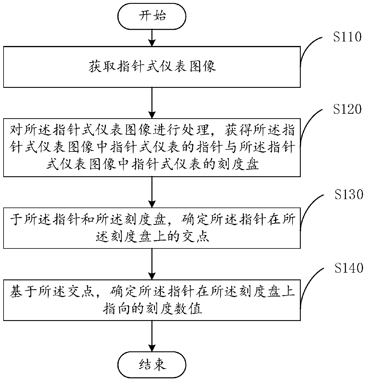
[0076] Please refer to figure 1 , figure 1 A flow chart of a pointer instrument scale identification method provided in the embodiment of the present application, including:
[0077] Step S110: Obtain the image of the pointer instrument to be recognized.
[0078] In the embodiment of the present application, the processor obtains the image of the pointer instrument to be recognized by the camera device installed in the industrial system through wired transmission or wireless transmission; of course, the processor can also obtain the pointer instrument The recorded video screen, at this time, the pointer instrument image to be recognized is the pointer instrument image at a specific moment in the video screen. The pointer instrument image may include a complete dial and pointer, so as to improve the accuracy of subsequent recognition of the pointer instrument image.
[0079] Step S120: Process the pointer meter image to obtain a pointer image including the pointer of the poi...
Embodiment 2
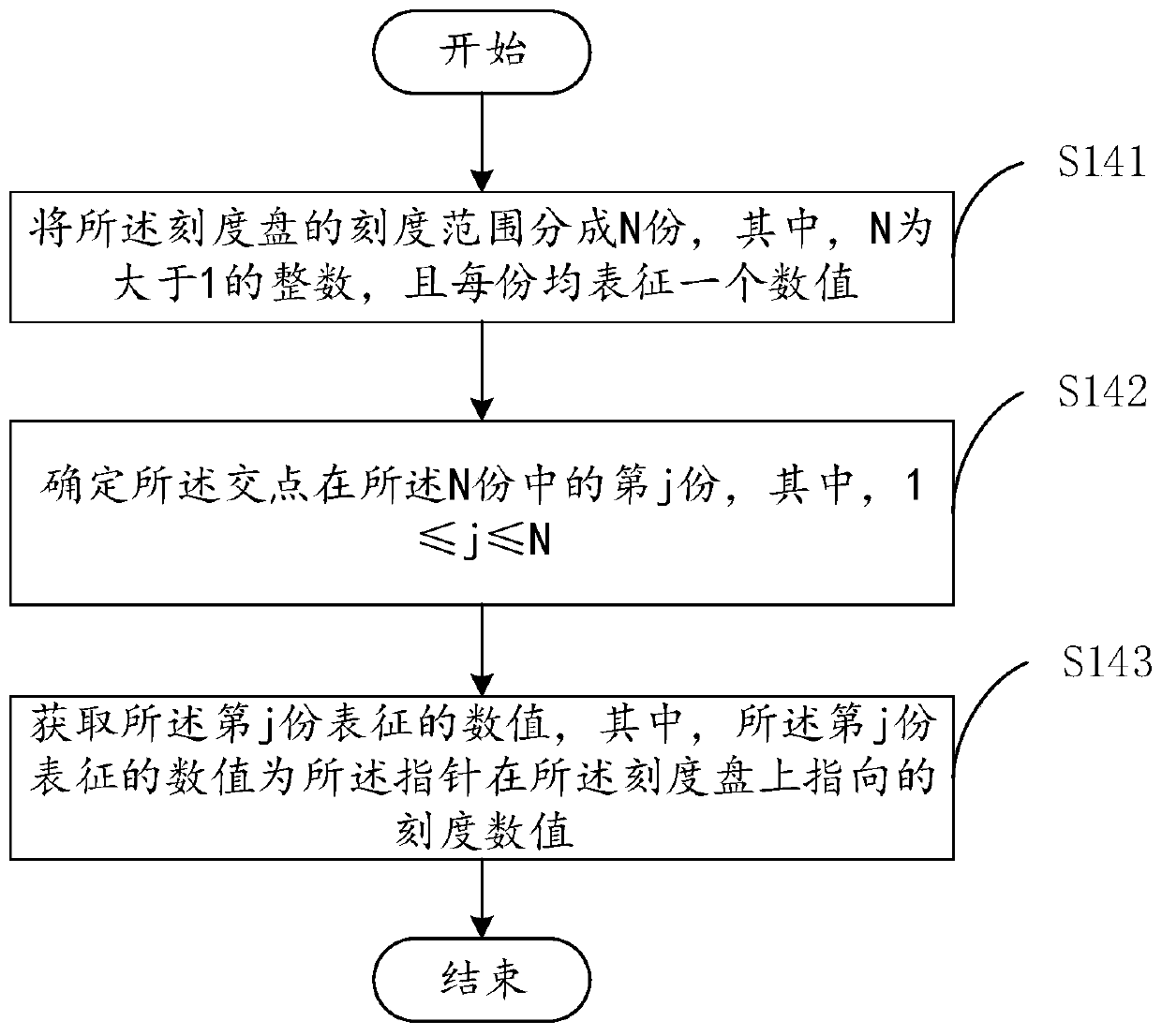
[0103] Next, on the basis of the first embodiment, how to obtain the scale value pointed by the pointer in the pointer meter image will be described in more detail. see figure 2 , as an implementable manner, step S140: (based on the position of the intersection point on the partial dial, determine the scale value pointed to by the pointer on the pointer instrument), specifically, it may be:
[0104] Step S141: Divide the scale range of the partial dial into N parts, where N is an integer greater than 1, and each part represents a numerical value.
[0105] In order to better explain the idea provided by the present application, a part of the dial is an example for the whole of the dial. In the embodiment of the present application, the scale range can be divided into N parts according to the scale specification of the dial, but the division method is not limited, it only needs to be able to represent a scale value for each divided part. For example: if the dial is a fan-shap...
Embodiment 3
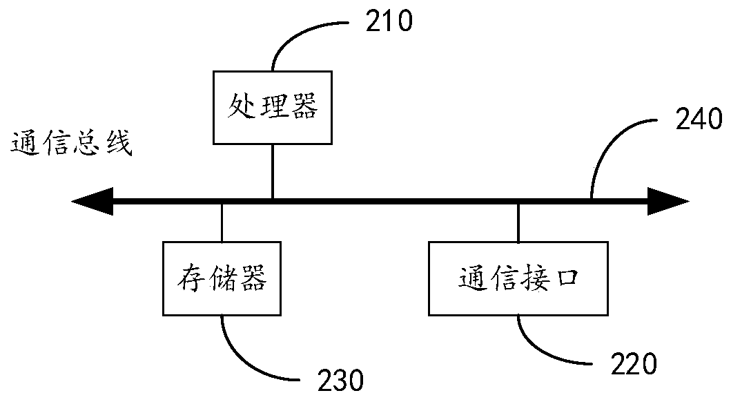
[0129] Optionally, see image 3 , image 3 The electronic device provided in the embodiment of the present application is a schematic structural diagram, and the electronic device may include: at least one processor 210 , such as a CPU, at least one communication interface 220 , at least one memory 230 and at least one communication bus 240 . Wherein, the communication bus 240 is used to realize the direct connection and communication between the processor and the camera device or between the equipment and the camera device. Wherein, the communication interface 220 of the device in the embodiment of the present application is used for signaling or data communication with other node devices (such as a device and a camera). The memory 230 may be a high-speed RAM memory, or a non-volatile memory (non-volatile memory), such as at least one disk memory. Optionally, the memory 230 may also be at least one storage device located far away from the aforementioned processor. Computer...
PUM
 Abstract
Description
Claims
Application Information
 - R&D
- Intellectual Property
- Life Sciences
- Materials
- Tech Scout
- Unparalleled Data Quality
- Higher Quality Content
- 60% Fewer Hallucinations
Browse by: Latest US Patents, China's latest patents, Technical Efficacy Thesaurus, Application Domain, Technology Topic, Popular Technical Reports.
© 2025 PatSnap. All rights reserved.Legal|Privacy policy|Modern Slavery Act Transparency Statement|Sitemap|About US| Contact US: help@patsnap.com


