
Overhead line discharge breakdown fault monitoring apparatus and method

An overhead line and discharge breakdown technology, which is applied in the direction of fault location, fault detection according to conductor type, and dielectric strength test, can solve problems such as unstable operation, high cost, and false alarms of fault monitoring devices, and reduce fault finding Difficulty, the effect of saving manpower and material resources

Active Publication Date: 2019-12-31
STATE GRID HUNAN ELECTRIC POWER +2
View PDF14 Cites 3 Cited by
  • Summary
  • Abstract
  • Description
  • Claims
  • Application Information

AI Technical Summary

Problems solved by technology

The use of the overhead line discharge breakdown fault monitoring device and method can not only effectively determine the location of the line discharge breakdown fault point, but also reduce the difficulty of fault finding by operation and maintenance personnel, save manpower and material resources, and solve the problem of unstable operation of the current fault monitoring device. Costly and potentially false positive technical issues

Method used


Image

  • Overhead line discharge breakdown fault monitoring apparatus and method

Examples


Embodiment 1

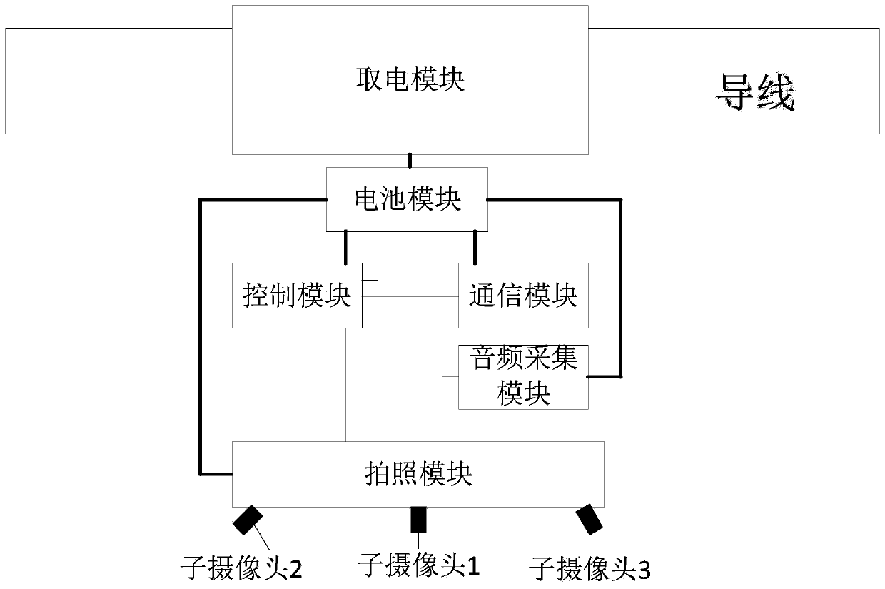
[0021] see figure 1 , this embodiment includes a power-taking module, a battery module, a control module, an audio collection module, a camera module and a communication module. The power-taking module is installed on the overhead line, and takes power from the overhead line to charge the battery module. The battery module supplies power to other modules except the power-taking module. The control module monitors the charging connection status between the power-taking module and the battery module. The acquisition module collects the ambient sound and sends it to the control module to determine the volume of the ambient sound. The camera module communicates with the control module and takes pictures under the control of the control module and transmits them to the control module. The communication module receives the information that needs to be sent provided by the control module and sent to the remote control center. The power-taking module continues to charge the battery m...

Embodiment 2

[0024] The device of this embodiment is basically the same as that of Embodiment 1, except for the camera module. The photographing module of this embodiment adopts a rotating camera. When it is necessary to take pictures, the rotating camera rotates from one side to the other, and the images taken during the rotation are synthesized into a seamless panorama photo, which can be combined with The shooting of the panorama photo is completed as in Embodiment 1.

[0025] When using the above-mentioned device to monitor the discharge breakdown fault of the overhead line, the following steps are included:

[0026] Step 1, real-time acquisition of overhead line power transmission conditions and ambient volume conditions at the monitoring location;

[0027] Step 2, when the power transmission of the overhead line is interrupted and the ambient volume reaches the preset volume decibel value, a warning message is sent to the control center;

[0028] Step 3: collect the image of the mo...


PUM


Abstract

The present invention discloses an overhead line discharge breakdown fault monitoring apparatus and method. The overhead line discharge breakdown fault monitoring apparatus comprises a power taking module, a battery module, a control module, an audio acquisition module, a photographing module, and a communication module. The power taking module is arranged on an overhead line, and takes power fromthe overhead line to charge the battery module; the battery module supplies power to other modules excluding the power taking module; and the control module communicates with other modules. The technical effects of the apparatus and method provided by the present invention are that: 1), a point location of a line discharge breakdown fault can be effectively determined; 2), whether the fault belongs to a fault type such as mountain fire, construction and the like can be initially determined and the original picture evidence can be obtained; and 3), difficulty of finding faults can be reduced for the operation and maintenance personnel, and manpower and resources can be saved.

Description

technical field [0001] The invention belongs to the technical field of electric power engineering, and in particular relates to an overhead line discharge breakdown fault monitoring device and method. Background technique [0002] Overhead line wire-to-wire, wire-to-ground wire, wire-to-line objects, wire-to-crossarm, and wire-to-tower discharge breakdown will cause line power outages. According to the requirements of the power operation department in the actual production work, the cause of the power failure of the line must be found out, and the clear discharge point of the wire must be found. Therefore, whenever a power outage is caused by a discharge breakdown fault on the line, the power operation department will arrange special personnel to check the line and confirm the discharge point. Usually, the measures taken are pole inspection and drone-assisted search. The problem is that the former requires a lot of manpower and material resources, because the reference faul...

Claims


Application Information

Patent Timeline
Patent Type & Authority Applications(China)
IPC IPC(8): G01R31/08G01R31/12
CPCG01R31/085G01R31/1209
Inventor 巢亚锋
Owner STATE GRID HUNAN ELECTRIC POWER
Learn More