Roller coating production process
A production process, roller coating technology, applied in the direction of coating, surface coating liquid device, pretreatment surface, etc., can solve problems such as roller coating pockmarks, and achieve the effect of improving quality and improving effect
- Summary
- Abstract
- Description
- Claims
- Application Information
AI Technical Summary
Problems solved by technology
Method used
Image

Examples
Embodiment 1
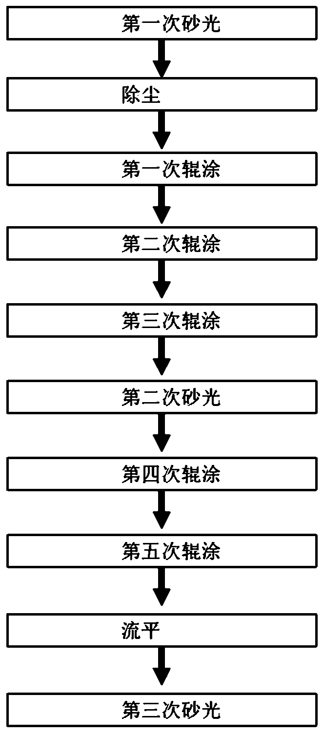
[0033] Embodiment one: as attached figure 1 Shown: Roller coating production process, including the following steps,
[0034] A. The first sanding step: use a wood sander to sand the door panel;
[0035] B. Dust removal step: Use an electrostatic dust collector to perform electrostatic dust removal on the polished and sanded door panels;
[0036] C. The first roller coating step: Use a roller coating device to roll coat the dust-removed door panel. The specific steps are: S1: Use a paint bucket to provide paint to the paint pump; S2: Use a paint pump to replenish paint to the coating mechanism ; S3: use the conveyor belt to transport the wooden board to the lower side of the coating mechanism; S4: use the coating mechanism to coat the door panel with a paint film; then use a UV curing machine to cure the paint film;
[0037] D, the second roll coating step: use a roll coating device and an ultraviolet curing machine to roll coat the door panel after the first roll coating an...
Embodiment 2
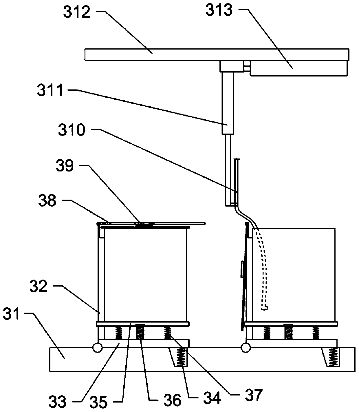
[0047] Embodiment two: the difference with embodiment one is only: as image 3 As shown, two paint bucket placement racks are arranged on the support 31, and the two paint bucket placement racks are arranged side by side along the swing direction of the support plate 33; 35. The upper side of the moving plate 35 is provided with a positioning groove for placing paint buckets; three supporting springs 37 are connected between the moving plate 35 and the supporting plate 33, and the three supporting springs 37 are distributed in a triangle; the upper side of the supporting plate 33 passes through The bolt is connected with an electromagnet 36, and the lower side of the moving plate 35 is welded with a ferromagnetic block cooperating with the electromagnet 36; the free end of the suction conduit 310 is connected with a liquid level switch, and the liquid level switch is electrically connected with the circuit of the electromagnet 36; The notch of the limit groove of the stop bar ...
Embodiment 3
[0049] Embodiment three: the difference with embodiment two is only: as Figure 5 Shown, the bottom of support 31 is connected with guide rail 315 along lateral sliding, and electric cylinder 314 is connected between the left part of guide rail 315 and the left part of support 31; The connecting rod and the guide rail 315 are welded and fixed, and the vertical sliding rod 316 is slid vertically connected to the fixed frame 317. The lower part of the sliding rod 316 is axially provided with a placement chamber for placing the suction conduit 310, and the lower end of the placement chamber runs through The lower end of the sliding rod 316, the free end of the suction conduit 310 is flush with the lower end of the sliding rod 316; the lower end of the sliding rod 316 is fixedly equipped with a push switch, the push switch is electrically connected with the electromagnet 36, and the push switch is electrically connected with the electric cylinder 314 ; The sliding rod 316 is provi...
PUM
 Abstract
Description
Claims
Application Information
 - R&D
- Intellectual Property
- Life Sciences
- Materials
- Tech Scout
- Unparalleled Data Quality
- Higher Quality Content
- 60% Fewer Hallucinations
Browse by: Latest US Patents, China's latest patents, Technical Efficacy Thesaurus, Application Domain, Technology Topic, Popular Technical Reports.
© 2025 PatSnap. All rights reserved.Legal|Privacy policy|Modern Slavery Act Transparency Statement|Sitemap|About US| Contact US: help@patsnap.com