
A step-by-step drug delivery device

A drug delivery device and a drug delivery technology, which are applied in the field of biomedical experimental devices, and can solve the problems of drug delivery, the inability to embed microelectrode arrays, and the inability to achieve more comprehensive drug delivery.

Active Publication Date: 2021-05-18
SHENZHEN INST OF ADVANCED TECH CHINESE ACAD OF SCI
View PDF6 Cites 0 Cited by
  • Summary
  • Abstract
  • Description
  • Claims
  • Application Information

AI Technical Summary

Problems solved by technology

[0007] However, because the catheter is fixed in this way, it can only be administered to a fixed position, and one such device cannot be administered to multiple positions, and cannot achieve more comprehensive drug delivery; and the current method takes up Excessive volume, after implantation of catheters in the brain it is no longer possible to embed microelectrode arrays for signal recording, which makes accurate recording of neuronal electrical signals impossible, for example after acute drug administration

Method used


Image

  • A step-by-step drug delivery device
  • A step-by-step drug delivery device
  • A step-by-step drug delivery device

Examples


Embodiment 1

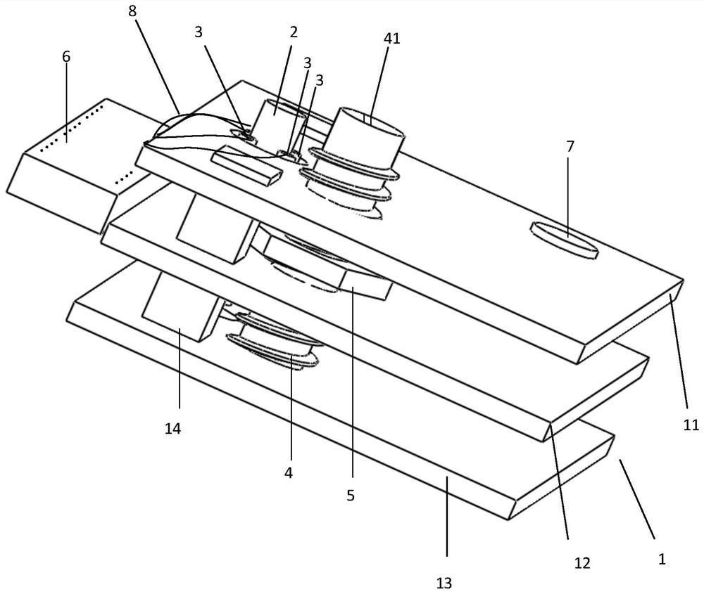
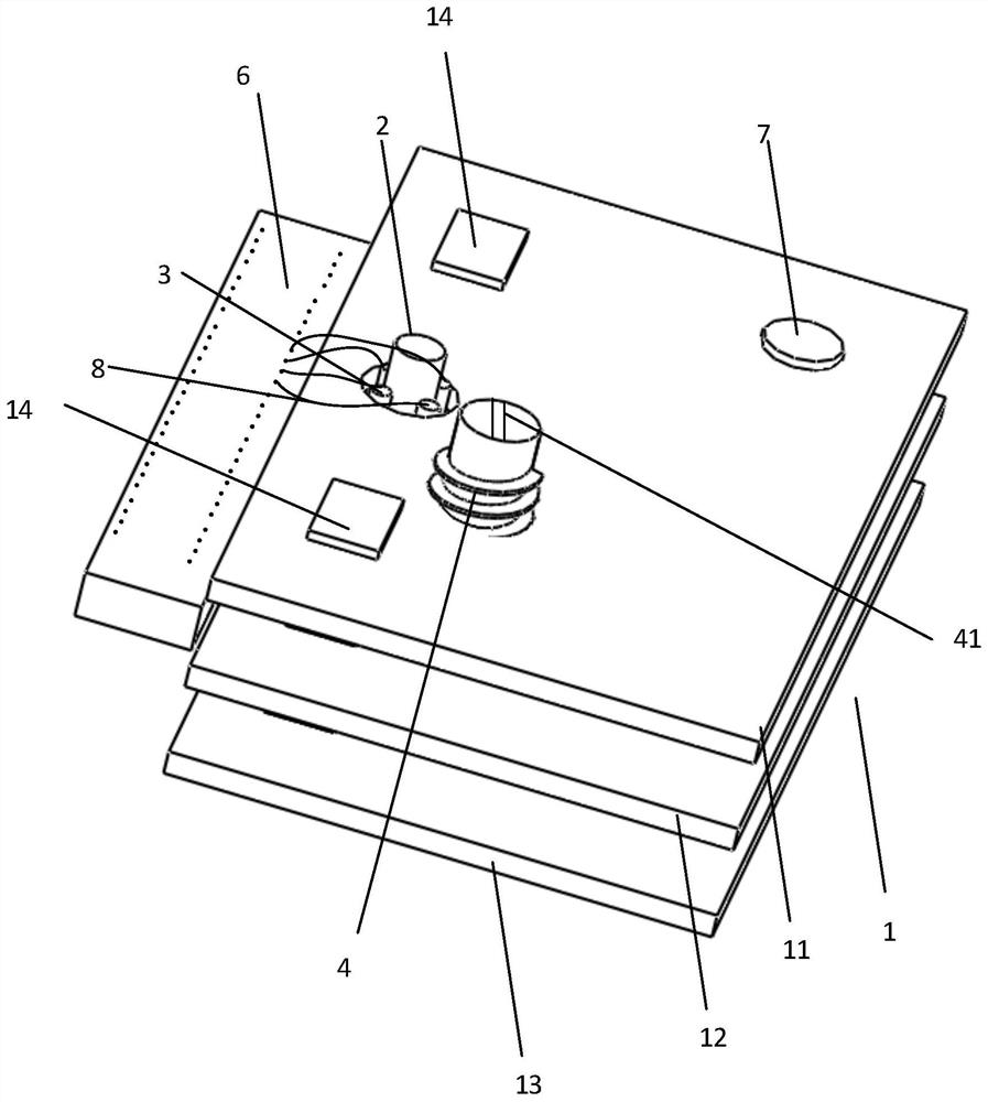
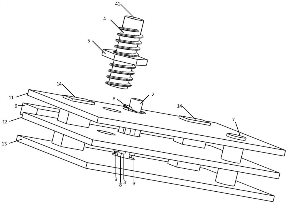
[0051] Embodiments of the present invention provide a step-by-step drug delivery device, such as Figure 1-6 As shown, it includes: a bearing assembly 1, and a drug delivery catheter 2 connected to the bearing assembly 1, a plurality of wire tubes 3, a threaded rod 4, a nut 5 fitted with the threaded rod 4, and used for recording neuron signals The signal recorder 6 and the connecting rod 7 for connecting an external stereotaxic instrument;

[0052] Wherein, the middle part of the threaded rod 4 is sleeved with a nut 5, the lower end of the threaded rod 4 contacts the lower inner wall of the bearing assembly 1, and the upper end of the threaded rod 4 penetrates the upper part of the bearing assembly 1, so The upper end of the threaded rod 4 is provided with a drive structure 41; the bearing assembly 1 is also provided with a limiter for limiting the rotation of the nut 5, so that when the threaded rod 4 rotates, the nut 5 can move up and down. move;

[0053] Specifically, th...

Embodiment 2

[0086] This embodiment 2 is the same as the previous embodiment 1 except for the carrying assembly 1. Specifically, in this embodiment, the carrying assembly 1 includes: a first support plate 11 located at the upper end, a first support plate 11 located at the lower end The second support plate 13, column 14; wherein,

[0087] Both the first support plate 11 and the second support plate 13 are provided with conduit connection holes, rod connection holes, and column connection holes;

[0088] The drug delivery catheter 2 fixedly connected with a plurality of wire tubes 3 respectively passes through the catheter connection holes on the first support plate 11 and the second support plate 13 to realize connection with the bearing assembly 1; The connecting rods 7 respectively pass through the rod connection holes on the first support plate 11 and the second support plate 13 to achieve a fixed connection with the bearing assembly 1; the uprights 14 respectively pass through the fir...


PUM


Abstract

The present invention proposes a step-by-step drug delivery device, comprising: a load-bearing assembly, a drug delivery catheter, a wire tube, a threaded rod, a nut, a signal recorder and a connecting rod; wherein, a nut is sleeved in the middle of the threaded rod, and the threaded rod The lower end of the threaded rod contacts the lower inner wall of the bearing assembly, the upper end of the threaded rod penetrates the upper part of the bearing assembly, and the upper end of the threaded rod is provided with a driving structure; the bearing assembly is also provided with a stopper for limiting the rotation of the nut, so that when the threaded rod rotates , to realize the up and down movement of the nut; when the nut moves up and down, it drives the drug delivery catheter to move up and down. Through this device, the stepping of the drug delivery catheter can be realized, so that a larger area can be administered, and in this solution, an electrode wire for detecting neuronal signals is attached to the drug delivery catheter, thereby realizing drug delivery It is integrated with signal detection, and can detect the area where the drug is administered in a targeted manner, and the signal acquisition is more timely and targeted, so that the acquired signal is more accurate.

Description

technical field [0001] The invention relates to the field of biomedical experiment devices, in particular to a step-by-step drug delivery device. Background technique [0002] In biological experiments, there are many methods of drug administration for experimental animals, such as intraperitoneal injection, intravenous injection, and gavage. However, for the study of brain nerves and brain diseases, the above administration methods have serious deficiencies: [0003] First, some drugs cannot pass through the blood-brain barrier and fail to achieve the expected effect; [0004] Second, the dosage is small, generally a few microliters or even less. [0005] The traditional way of drug administration for experimental animals is limited in targeting neurological and brain diseases. [0006] For this reason, a central nervous system administration method has also been developed, which is mostly used for the response of target nuclei or brain regions to drugs. At present, the ...

Claims


Application Information

Patent Timeline
Patent Type & Authority Patents(China)
IPC IPC(8): A61D7/00A61B5/00A61B5/273A61B5/294A61B5/388
CPCA61B5/4839A61B5/685A61B5/6868A61B2503/40A61B2503/42A61B2562/0209A61B2562/125A61D7/00A61B5/24
Inventor 吕丹詹阳孙语遥欧阳雨林
Owner SHENZHEN INST OF ADVANCED TECH CHINESE ACAD OF SCI
Learn More