Eureka AIR delivers breakthrough ideas for toughest innovation challenges, trusted by R&D personnel around the world.

High-density resistivity method electrode suitable for open iron mine stope

A technology of high-density resistivity and iron ore, which is applied in the direction of re-radiation, electric/magnetic exploration, and re-radiation of sound waves, etc., can solve the problem of affecting the accuracy of data collection, the deterioration of the conductive contact between the electrode and the earth, and the inability of the electrode to be completely Insert problems such as the ground surface to ensure the accuracy of data collection and improve the effect of conductive contact

Active Publication Date: 2019-12-27
NORTHEASTERN UNIV
View PDF15 Cites 0 Cited by
  • Summary
  • Abstract
  • Description
  • Claims
  • Application Information

AI Technical Summary

Problems solved by technology

[0006] However, during the electrode laying process, since there is no shelter in the open-pit iron mine stope, the electrodes will be exposed to sunlight for a long time. The water is easily volatilized, resulting in the inability to maintain a relatively humid environment between the electrode and the ground, resulting in poor electrical contact between the electrode and the ground, and ultimately affecting the accuracy of data collection
[0007] Furthermore, if the ground surface at the measurement point is a hard rock base, the electrodes of the traditional high-density resistivity method cannot be fully inserted into the ground surface, which will also affect the overall quality of the data

Method used


Image

  • High-density resistivity method electrode suitable for open iron mine stope

Examples


Embodiment Construction

[0017] The present invention will be further described in detail below in conjunction with the accompanying drawings and specific embodiments.

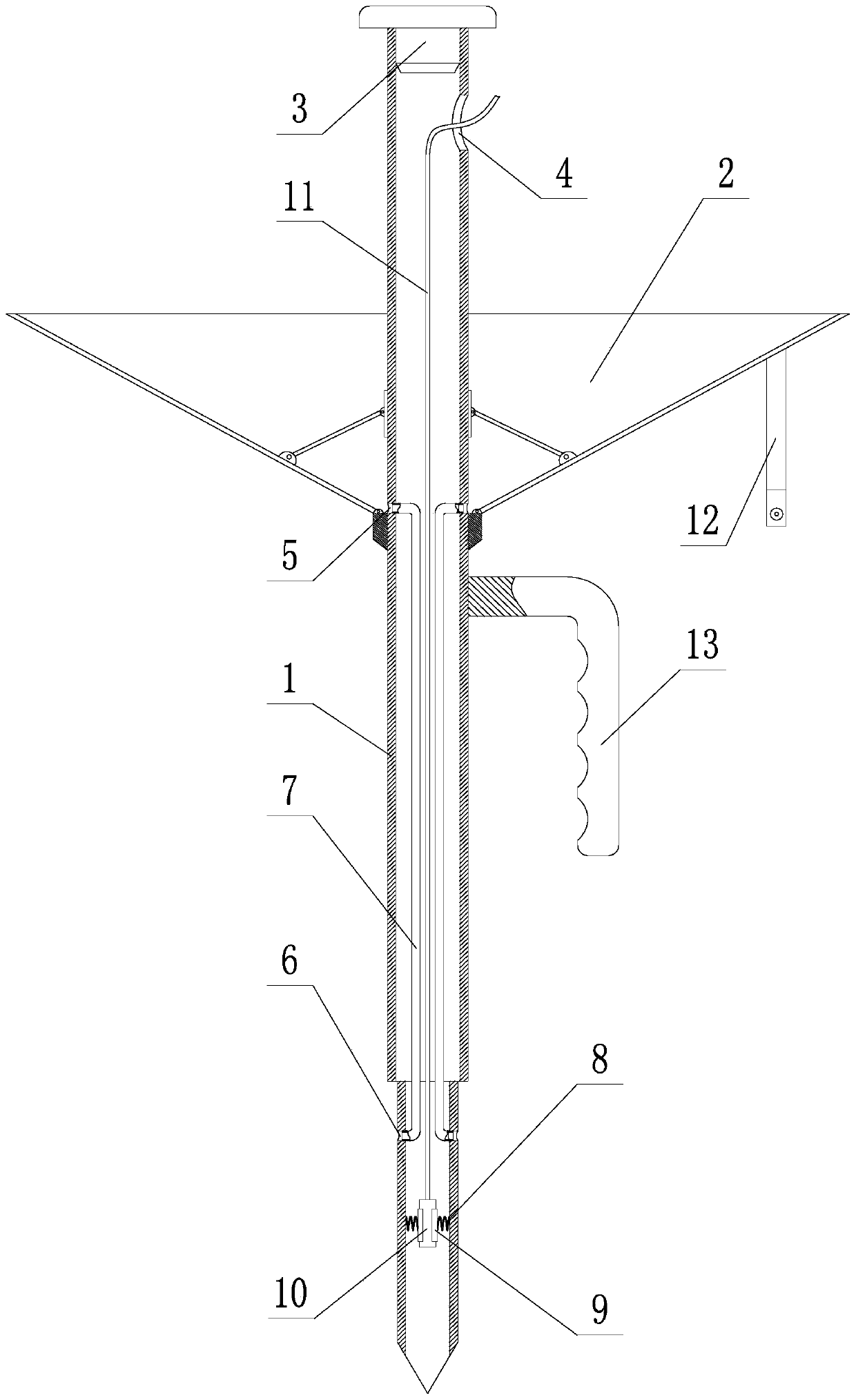
[0018] Such as figure 1 As shown, a high-density resistivity method electrode suitable for open-pit iron ore stope includes a hollow rod body 1 and a light shield 2, a hammer cap 3 is installed on the top of the hollow rod body 1, and the hollow body below the hammer cap 3 A wire outlet hole 4 is provided on the rod body 1, and the shading cover 2 is arranged on the hollow rod body 1 below the wire outlet hole 4; Pyramid structure; the shading cover 2 adopts a funnel-shaped structure, and a water injection hole 5 is opened on the hollow rod body 1 corresponding to the inner bottom of the shading cover 2, and a water outlet hole 6 is opened on the pyramid surface of the hollow rod body 1 entering the ground. 5 and the water outlet hole 6 are connected with a water guide pipe 7; a spring 8 is installed in the central channel of the hol...


PUM


Abstract

The invention discloses a high-density resistivity method electrode suitable for an open iron mine stope. The electrode comprises a hollow rod body and a sunshade, wherein a hammering cap is arrangedat the top end of the hollow rod body, a wire outlet hole is formed in the hollow rod body and located below the hammering cap, and the sunshade is arranged below the wire outlet hole; the bottom endof the hollow rod body is a ground insertion end and is of a triangular pyramid structure; the sunshade is in a funnel shape, a water injection hole is formed in the hollow rod body and located at thebottom of the inner side of the sunshade, a pyramid surface of the ground insertion end of the hollow rod body is provided with a water outlet hole, and the water injection hole communicates with thewater outlet hole through a water conduit; three springs uniformly distributed in a circumferential direction are installed in a central hole channel of the ground insertion end of the hollow rod body, one end of each spring is welded to the inner wall of the center hole channel, and the other end of each spring is welded to a clamping plate; a binding post is clamped among the three clamping plates, one end of a wire is welded to the binding post, and the other end of the wire extends out of the hollow rod body through the wire outlet hole; the sunshade is provided with folding ribs in a matched mode and is unfolded or folded through the folding ribs, and a binding strap is arranged on the outer surface of the sunshade; and a handle is arranged on the hollow rod body and located below the sunshade.

Description

technical field [0001] The invention belongs to the technical field of goaf detection in open-pit iron ore stopes, and in particular relates to a high-density resistivity electrode suitable for open-pit iron ore stopes. Background technique [0002] In the process of mineral resource development and utilization, due to random mining and indiscriminate mining and the transformation of scattered mining into overall mining in the process of mining integration, there are many unknown goafs in and around many mines, and these unknown goafs There is no detailed geological data, and some goafs may have been filled with water and deformed, and these unknown goafs are seriously affecting the daily production of the mine, and are always threatening the safety of stope workers and equipment. Therefore, how to accurately detect gobs has become one of the security problems that open-pit iron ore stopes must face at this stage. [0003] At present, the high-density resistivity method is ...

Claims


Application Information

Patent Timeline
Patent Type & Authority Applications(China)
IPC IPC(8): G01N27/04G01V3/00
CPCG01N27/041G01V3/00Y02A90/30
Inventor 宋坤郭凯王恩德付建飞贾三石尤欣慰马思顺
Owner NORTHEASTERN UNIV
Why Eureka
Eureka Blog
Learn More