Eureka AIR delivers breakthrough ideas for toughest innovation challenges, trusted by R&D personnel around the world.

Mechanical equipment fault diagnosis device capable of detecting vibration frequency

A technology for fault diagnosis devices and mechanical equipment, which is applied in measuring devices, testing of machines/structural components, and measurement of ultrasonic/sonic waves/infrasonic waves, etc. It can solve problems such as lack of good defense devices, easy misjudgment, damage to fault diagnosis devices, etc. , to achieve the effect of being convenient for multi-angle placement, reducing damage to the body, and being easy to carry

Inactive Publication Date: 2019-12-27
CHONGQING TECH & BUSINESS UNIV
View PDF4 Cites 1 Cited by
  • Summary
  • Abstract
  • Description
  • Claims
  • Application Information

AI Technical Summary

Problems solved by technology

[0004] The purpose of the present invention is to provide a mechanical equipment fault diagnosis device that can detect the vibration frequency, so as to solve the problem that the existing fault diagnosis device proposed in the above background technology has no frequency amplification equipment during use, resulting in too small vibration amplitude. Misjudgment is easy to occur, and there is no good defense device in use, which leads to the problem that the fault diagnosis device is prone to damage

Method used


Image

  • Mechanical equipment fault diagnosis device capable of detecting vibration frequency
  • Mechanical equipment fault diagnosis device capable of detecting vibration frequency
  • Mechanical equipment fault diagnosis device capable of detecting vibration frequency

Examples


Embodiment Construction

[0026] The technical solutions in the embodiments of the present invention will be clearly and completely described below in conjunction with the accompanying drawings in the embodiments of the present invention. Obviously, the described embodiments are only some of the embodiments of the present invention, not all of them. Based on The embodiments of the present invention and all other embodiments obtained by persons of ordinary skill in the art without making creative efforts belong to the protection scope of the present invention.

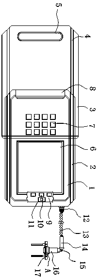
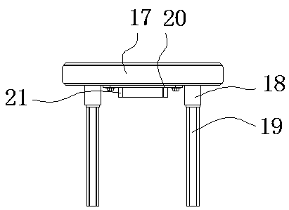
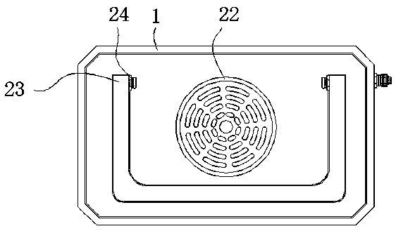
[0027] see Figure 1-5 , the present invention provides a technical solution: a mechanical equipment fault diagnosis device capable of detecting vibration frequency, including a body 1, a slot 2, a cover 3, an inner slide rail 4, a handle 5, a display screen 6, and an operation panel 7. Limit pad 8, PCB board 9, LED light 10, photosensitive sensor 11, fixed end 12, spring wire 13, connector 14, rotating arm 15, vibration detection probe 16, fixe...


PUM


Abstract

The invention relates to a mechanical equipment fault diagnosis device capable of detecting the vibration frequency. The mechanical equipment fault diagnosis device comprises a machine body and a display screen, wherein open grooves are distributed in two sides of an outer wall of the machine body; a cover body is distributed outside the open grooves; an inner sliding rail is distributed at the connected part of the cover body and the machine body; a handle is arranged at the middle part of one side of the cover body; the display screen is distributed at one side of the front side of the machine body; an operation panel is arranged at the other side of the front side of the machine body; a limiting pad is fixed at one end of the outer wall of the machine body; and a PCB is fixed in the display screen. Through the arrangement of the machine body, the open grooves and the cover body, a sliding structure is formed between the machine body and the cover body through the open grooves, and an obtuse angle design is adopted by the outer surface of the whole machine body, so that when a user holds the device, no sharp part exists at the corner of the device and the condition that the useris scratched is avoided; and furthermore, the cover body has a good protection effect and can effectively protect the front side of the machine body, thereby reducing the possibility of damage to themachine body in the carrying process.

Description

technical field [0001] The invention relates to the technical field of mechanical equipment fault detection, in particular to a mechanical equipment fault diagnosis device capable of detecting vibration frequency. Background technique [0002] Mechanical fault diagnosis is a technology to understand and master the state of the machine during operation, to determine its overall or partial normal or abnormal, to detect faults and their causes early, and to predict the development trend of faults. Oil monitoring, vibration monitoring, noise monitoring , performance trend analysis and non-destructive flaw detection are the main diagnostic techniques. A well-designed machine has a low natural vibration level, but when the machine wears, the foundation sinks, and the components deform, the dynamics of the machine Performance starts to change in all sorts of small ways: shafts become misaligned, components start to wear, rotors become unbalanced, gaps increase, all of these factors...

Claims


Application Information

Patent Timeline
Patent Type & Authority Applications(China)
IPC IPC(8): G01M99/00G01H17/00
CPCG01H17/00G01M99/005
Inventor 杨帅杨艺陈志强孔丽杰汪羽
Owner CHONGQING TECH & BUSINESS UNIV
Why Eureka
Eureka Blog
Learn More