
Pressure measurement device for wing elasticity shrinkage similarity model of large-size transport plane

A technology similar to model and transport aircraft, applied in the field of wind tunnel test, can solve the problems of inability to directly install the pressure measuring tube, large deformation, difficult to achieve, etc., and achieve the effect of simple and convenient processing method, light weight and simple installation.

Pending Publication Date: 2019-12-27
DALIAN UNIV OF TECH
View PDF0 Cites 2 Cited by
  • Summary
  • Abstract
  • Description
  • Claims
  • Application Information

AI Technical Summary

Problems solved by technology

In order to ensure the validity of the pressure measurement results, the tube axis of the pressure measurement tube in the wind tunnel test model must be strictly perpendicular to the skin surface, and the deflection angle should be within plus or minus 1 degree, which is difficult to achieve in the actual production of the model
Moreover, models with similar wing elastic ratios generally have low stiffness and large deformation, so it is impossible to directly install pressure measuring tubes.

Method used


Image

  • Pressure measurement device for wing elasticity shrinkage similarity model of large-size transport plane
  • Pressure measurement device for wing elasticity shrinkage similarity model of large-size transport plane
  • Pressure measurement device for wing elasticity shrinkage similarity model of large-size transport plane

Examples


Embodiment Construction

[0013] The structure of the present invention will be further described below with reference to the accompanying drawings.

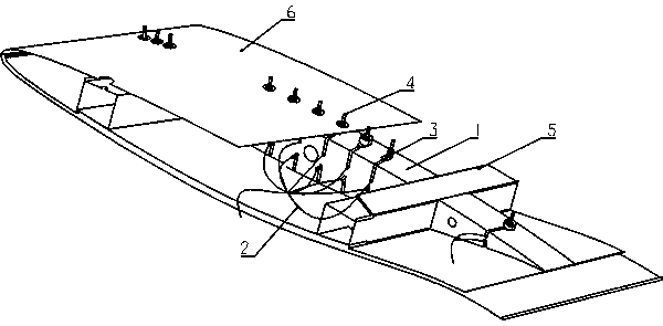
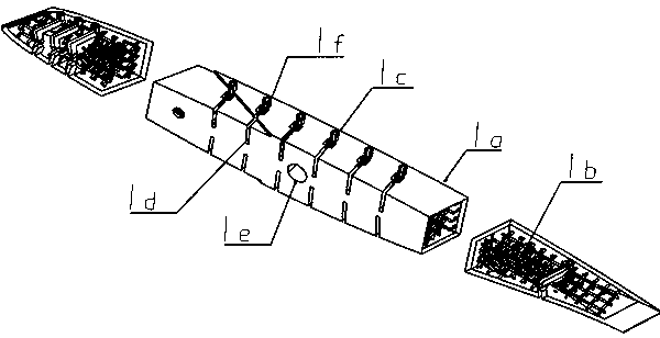
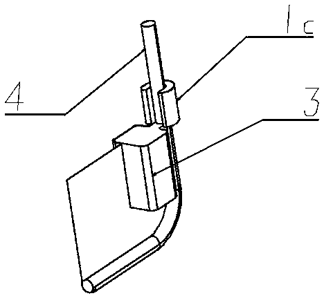
[0014] figure 1 , 2 , 3 show the schematic diagram of the structure of the pressure measuring device of the wind tunnel test model similar to the elastic ratio of the wing. In the figure, the pressure measuring device used for the similar model of large transport aircraft wing elastic reduction includes pressure measuring hose bracket 1, pressure measuring hose 2, top block 3, pressure measuring steel pipe 4, spar 5 and skin 6. The upper and lower surfaces of the pressure measurement hose bracket 1 are attached to the skin 6 and bonded to the skin 6 and the spar 5 by resin glue. The pressure measurement steel pipe 4 is connected to the pressure measurement hose 2, and the pressure measurement steel pipe 4 is built into the pressure measurement In the pressure measuring pipe groove 1d of the pipe bracket 1, the pressure measuring steel pipe 4 is fixed ...


PUM


Abstract

A pressure measurement device for wing elasticity shrinkage similarity model of a large-size transport plane belongs to the technical field of wind tunnel test. The pressure measurement device employsa pressure measurement pipe bracket formed by 3D printing, an upper surface and a lower surface are completely same as local wings of a part of which pressure is needed to be measured of a skin, theupper surface and the lower surface are pasted onto the skin and a wing beam by resin, a pressure measurement hose is connected with a pressure measurement steel pipe, the pressure measurement steel pipe is arranged in the pressure measurement pipe bracket and is fixed by a top block, half-cylinder bulges are arranged at pressure measurement positions of an upper surface and a lower surface of thepressure measurement pipe bracket and are matched with pressure measurement holes of a skin surface, the pressure measurement steel pipe extends out of the pressure measurement holes in the skin surface through a pipe groove of the pressure measurement pipe on the pressure measurement pipe bracket, and a pipe axis of the pressure measurement steel pipe is required to be perpendicular to the skinsurface. The pressure measurement device is simple to install, the pressure measurement pipe bracket is light in structural mass, obvious mass and rigidity cannot be added to the model, steady pressure distribution measurement of an upper surface and a lower surface of the model can be achieved in static aerodynamic elastic tunnel experiment, and the problem that the pressure measurement pipe is difficult to install in a wind elasticity similarity model is solved.

Description

technical field [0001] The invention relates to a pressure measuring device used for a large-scale transport aircraft wing elastic reduction ratio similar model, which belongs to the technical field of wind tunnel tests. Background technique [0002] In the static aeroelastic wind tunnel test, it is generally necessary to measure the steady pressure distribution of the model. The pressure measurement results can be used to test the reliability of the calculation method and serve as a reference or basis for improving the calculation method. A reasonable and effective wind tunnel test model pressure measurement system is an important basis for obtaining reliable research data. In order to ensure the validity of the pressure measurement results, the axis of the piezometric tube in the wind tunnel test model must be strictly perpendicular to the skin surface, and the deflection angle should be within plus or minus 1 degree, which is difficult to achieve in the actual production...

Claims


Application Information

Patent Timeline
Patent Type & Authority Applications(China)
IPC IPC(8): G01M9/06
CPCG01M9/06B33Y80/00B64C3/26B64F5/60G06F30/10
Inventor 钱卫葛少杰李星陈香言
Owner DALIAN UNIV OF TECH
Learn More