
The inner rail of the two-section server slide rail facilitates the installation structure

A technology for installing structures and servers. It is used in the installation of servers, supporting structures, and between data centers. It can solve problems such as troublesome use and difficult alignment of inner rails.

Active Publication Date: 2020-12-04
GSLIDE
View PDF12 Cites 0 Cited by
  • Summary
  • Abstract
  • Description
  • Claims
  • Application Information

AI Technical Summary

Problems solved by technology

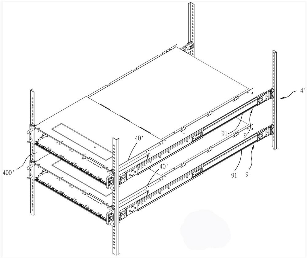
[0002] By server box 40' (such as figure 1 As shown) when the two-stage slide rail 9 is installed on the server rack 4', the outer rail 91 is first installed on the server rack 4', and then the inner rail combined by the server box 40' (not shown) Align the front end of the aforementioned outer rail 91 for installation, but after checking that the server rack 4' has been installed into the upper and lower two server boxes 40' through the two-section slide rail 9 respectively, if you want to install it in the future When another server box 40' is installed in the space 400' between the upper and lower server boxes 40' through another two-section slide rail 9, the front end of the outer rail 91 will be covered by the upper and lower server boxes. The case 40' covers the blind spot of the line of sight, and the inner rail combined with the server case 40' is difficult to be aligned with the front end of the corresponding outer rail 91 set on the server rack 4', resulting in huge use. troubled

Method used


Image

  • The inner rail of the two-section server slide rail facilitates the installation structure
  • The inner rail of the two-section server slide rail facilitates the installation structure
  • The inner rail of the two-section server slide rail facilitates the installation structure

Examples


Embodiment Construction

[0027] The present invention will be described in further detail below in conjunction with the accompanying drawings, but it is not intended to limit the present invention.

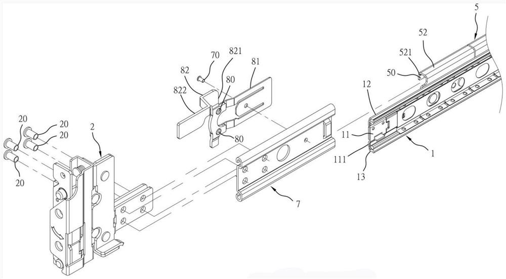
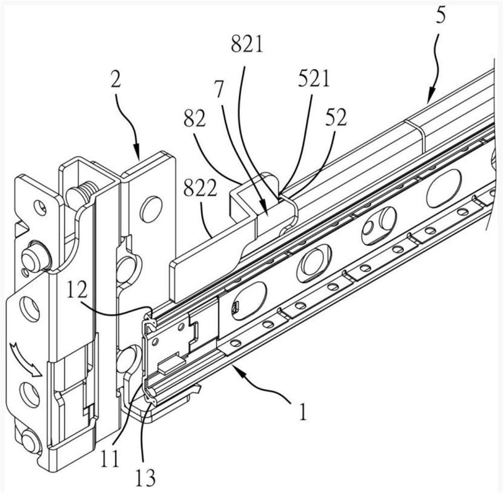
[0028] Such as Figure 2 to Figure 11 As shown, the present invention provides a convenient installation structure for the inner rail of a two-stage server slide rail, including:

[0029] An outer rail 1 has a main wall 11 and upper and lower walls 12, 13 connected to the upper and lower sides of the main wall 11;

[0030] One front and rear brackets 2, 3 (such as Figure 4 shown), are respectively installed on the server rack 4 by its front and rear ends, and wherein the front end of the rear bracket 3 is engaged and fixed with the rear end of the outer rail 1;

[0031] An outer rail reinforcement rail 5, comprising a main wall 51 (such as Figure 11 shown) and the upper and lower walls 52, 53 connected to the upper and lower sides of the main wall 51 to form a chute 50 in the front and rear direction...


PUM


Abstract

The invention provides a convenient installation structure for the inner rail of a two-section server slide rail. The front bracket of the outer rail is fixedly connected with the front end of a frontbracket auxiliary slide rail. The rear side of the front bracket auxiliary slide rail is slidably sleeved into the chute of an outer rail reinforcement rail. The rear side of the front bracket auxiliary slide rail is fixedly connected with one end of an elastic piece. The other end of the elastic piece is fixedly connected with an outer rail pull-out control member. The outer rail pull-out control member comprises a blocking portion which is used to block the front end of the upper wall of the outer rail reinforcement rail. The front side of the blocking portion is connected with a pressing portion. The pressing portion is pressed to apply force to enable the blocking portion to break away from the front end of the upper wall of the outer rail reinforcement rail. The outer rail reinforcement rail can be pulled outward and slide outward relative to the front direction of the front bracket auxiliary slide rail, and at the same time is pulled outward along with the outer rail for a distance. The front end of the outer rail is exposed to the front end of a server rack, so that the inner rail can be conveniently aligned and installed into the outer rail.

Description

【Technical field】 [0001] The invention refers to a convenient installation structure for the inner rail of a two-section server slide rail, and relates to a two-section server slide rail whose middle rail can be pulled out for a certain distance to expose the front end of the server rack to facilitate the installation of the inner rail. The related technical field of the convenient installation structure of the inner rail of the server box combined with the rail and the inner rail. 【Background technique】 [0002] By server box 40' (such as figure 1 As shown) when the two-stage slide rail 9 is installed on the server rack 4', the outer rail 91 is first installed on the server rack 4', and then the inner rail combined by the server box 40' (not shown) Align the front end of the aforementioned outer rail 91 for installation, but after checking that the server rack 4' has been installed into the upper and lower two server boxes 40' through the two-section slide rail 9 respectiv...

Claims


Application Information

Patent Timeline
Patent Type & Authority Patents(China)
IPC IPC(8): H05K7/14
CPCH05K7/1489
Inventor 陈永亮
Owner GSLIDE
Learn More