
Motor winding tensioning device

A tensioning device and winding technology, used in electromechanical devices, manufacturing motor generators, electrical components, etc., can solve the problems of affecting winding performance, occupying dust, and low stator winding performance, achieving good winding performance and reducing defective products. The effect of the appearance rate of

Pending Publication Date: 2019-12-24
广西飞能电机有限公司
View PDF0 Cites 0 Cited by
  • Summary
  • Abstract
  • Description
  • Claims
  • Application Information

AI Technical Summary

Problems solved by technology

The existing winding machine has no restrictions on the tension of the copper wire during the winding process, but simply winds the copper wire to the iron core according to the program setting, but in the production process, the copper wire is stretched under the condition of flattening The flatness of the wound copper wire will be better; when the copper wire is tied up in storage, it is easy to occupy dust or dirt on the surface, and direct winding will affect the performance of the winding. Generally, workers need to wipe it clean before winding, which is time-consuming and laborious; in production There are often broken wires in the machine, because the winding machine is winding multiple windings at the same time, when a winding is broken, the winding work of other windings will not stop, resulting in low performance of the processed stator windings, and It is difficult for workers to find such tiny flaws in the process of processing, and it will only be reflected after installation and use, which will seriously affect the production of the motor and the reputation of the manufacturer

Method used


Image

  • Motor winding tensioning device
  • Motor winding tensioning device

Examples


Embodiment Construction

[0017] Embodiments of the technical solutions of the present invention will be described in detail below in conjunction with the accompanying drawings. The following examples are only used to illustrate the technical solutions of the present invention more clearly, and therefore are only examples, rather than limiting the protection scope of the present invention.

[0018] In this application, terms such as "installation", "connection", "connection" and "fixation" should be interpreted in a broad sense, for example, it can be a fixed connection or a detachable connection, unless otherwise clearly specified and limited. , or integrated; it can be mechanically connected or electrically connected; it can be directly connected or indirectly connected through an intermediary, and it can be the internal communication of two components or the interaction relationship between two components. Those of ordinary skill in the art can understand the specific meanings of the above terms in ...


PUM


Abstract

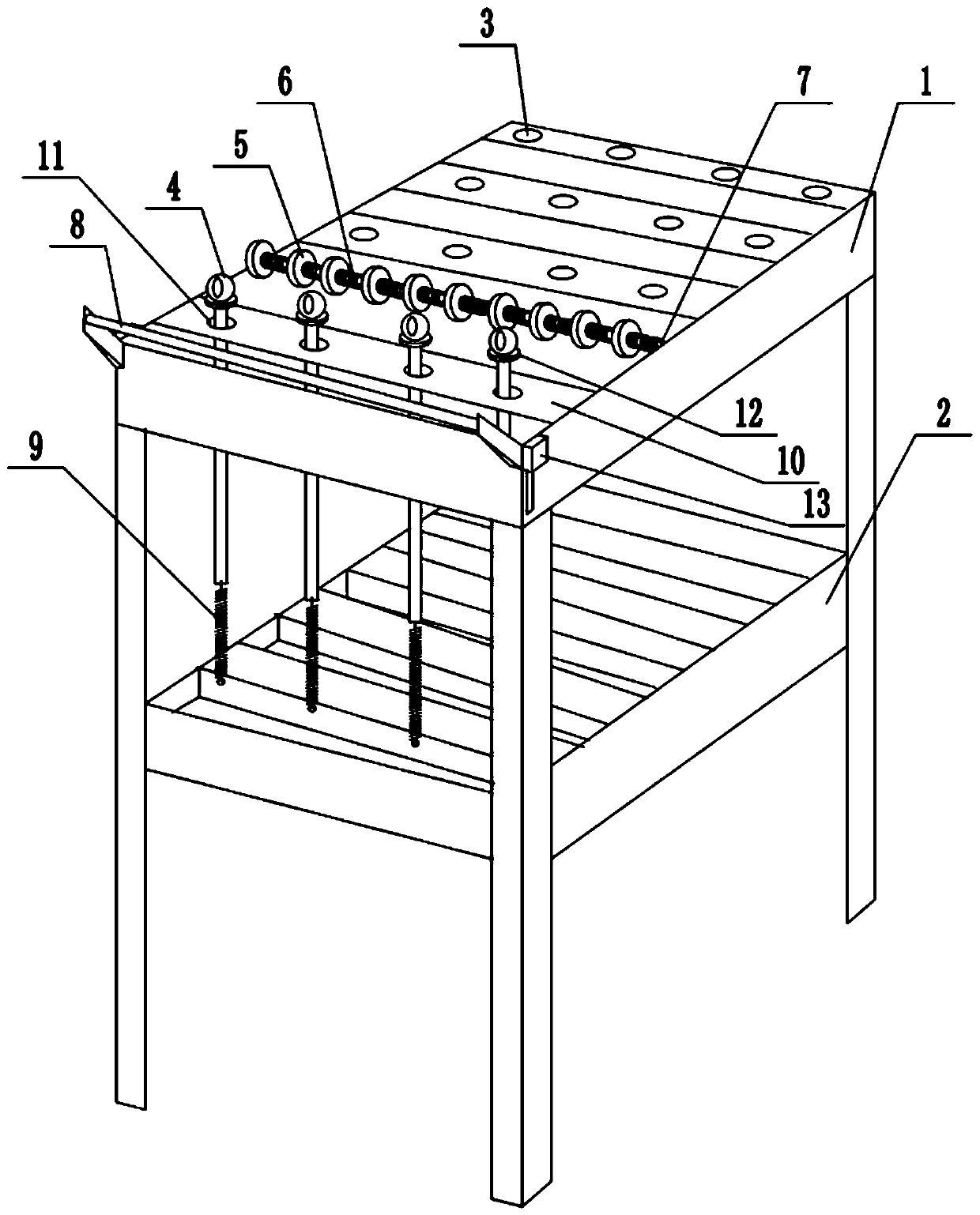
The invention provides a motor winding tensioning device which comprises a frame, a coil bracket, a flat cable hole, hanging needles, wire wipers, wire wiper springs, a rotating shaft, a positioning shaft, hanging needle springs, a hanging needle holder, hanging needle holes, a sensor and an alarm. The coil bracket is arranged in the frame. The flat cable hole is arranged in the crossbar on the top of the frame. The rotating shaft is arranged in the front of the top of the frame. A number of wire wipers are arranged on the rotating shaft. The wire wiper springs are arranged between the wire wipers. The hanging needle holder is located in front of the rotating shaft. The hanging needle holes are distributed in the hanging needle holder. After the hanging needles pass through the hanging needle holes, the bottoms of the hanging needles are connected with the hanging needle springs. The hanging needle springs are fixedly connected with the frame. The positioning shaft is located at the top edge of the frame in front of the hanging needle holder. The joint between the positioning shaft and the frame can be moved longitudinally. A sensor is arranged on the top of each hanging pin. The sensor output is connected with the alarm which is arranged on the frame.

Description

technical field [0001] The invention relates to the technical field of motor winding, in particular to a motor winding tensioning device. Background technique [0002] The stator winding is obtained by winding the copper wire on the stator core according to a certain method, and the winding is the processing process of the stator winding. The existing winding machine has no restrictions on the tension of the copper wire during the winding process, but simply winds the copper wire to the iron core according to the program setting, but in the production process, the copper wire is stretched under the condition of flattening The flatness of the wound copper wire will be better; when the copper wire is tied up in storage, it is easy to occupy dust or dirt on the surface, and direct winding will affect the performance of the winding. Generally, workers need to wipe it clean before winding, which is time-consuming and laborious; in production There are often broken wires in the m...

Claims


Application Information

Patent Timeline
Patent Type & Authority Applications(China)
IPC IPC(8): H02K15/08
CPCH02K15/08
Inventor 李同钢
Owner 广西飞能电机有限公司
Learn More