
PM2.5 monitor

A monitor and adjustment device technology, applied in the direction of instruments, measuring devices, scientific instruments, etc., can solve the problem of easy sticking of PM2.5 monitor precision parts, the reduction of PM2.5 monitor detection effect, and the reduction of PM2.5 monitor Problems such as service life, to avoid monitoring effects, improve sealing, and improve service life

Active Publication Date: 2019-12-24
河北球境环保科技有限公司
View PDF8 Cites 1 Cited by
  • Summary
  • Abstract
  • Description
  • Claims
  • Application Information

AI Technical Summary

Problems solved by technology

[0003] At present, there are hundreds of large and small construction sites under construction in the city every year. The branches are in every corner of the city. Many construction units neglect the management of the construction sites. In order to catch up with the schedule and compete for the construction period, the materials on the site are randomly piled up, and the construction process occurs. A large amount of PM2.5 has an impact on the urban environment. Therefore, it is stipulated that the construction site must install PM2.5 monitors to monitor the construction environment in real time, and it is not allowed to exceed the standard. However, the existing PM2.5 monitors on the site are exposed for a long time, which is not only easy Dust falls on the body of the PM2.5 monitor, resulting in inaccurate detection and being exposed to the outside, which is easy to collide and break. In severe weather, it is easy to make the particles in the air stick together, and the particles stick to the PM2.5 monitor, which not only reduces the detection effect of the PM2.5 monitor, but also makes it easier to stick to the precision inside the PM2.5 monitor. Parts, reduce the service life of the PM2.5 monitor, for this reason, a PM2.5 monitor is proposed to solve the above problems

Method used


Image

  • PM2.5 monitor
  • PM2.5 monitor
  • PM2.5 monitor

Examples


Embodiment Construction

[0022] In order to make the technical means, creative features, goals and effects achieved by the present invention easy to understand, the present invention will be further elaborated below in conjunction with specific embodiments.

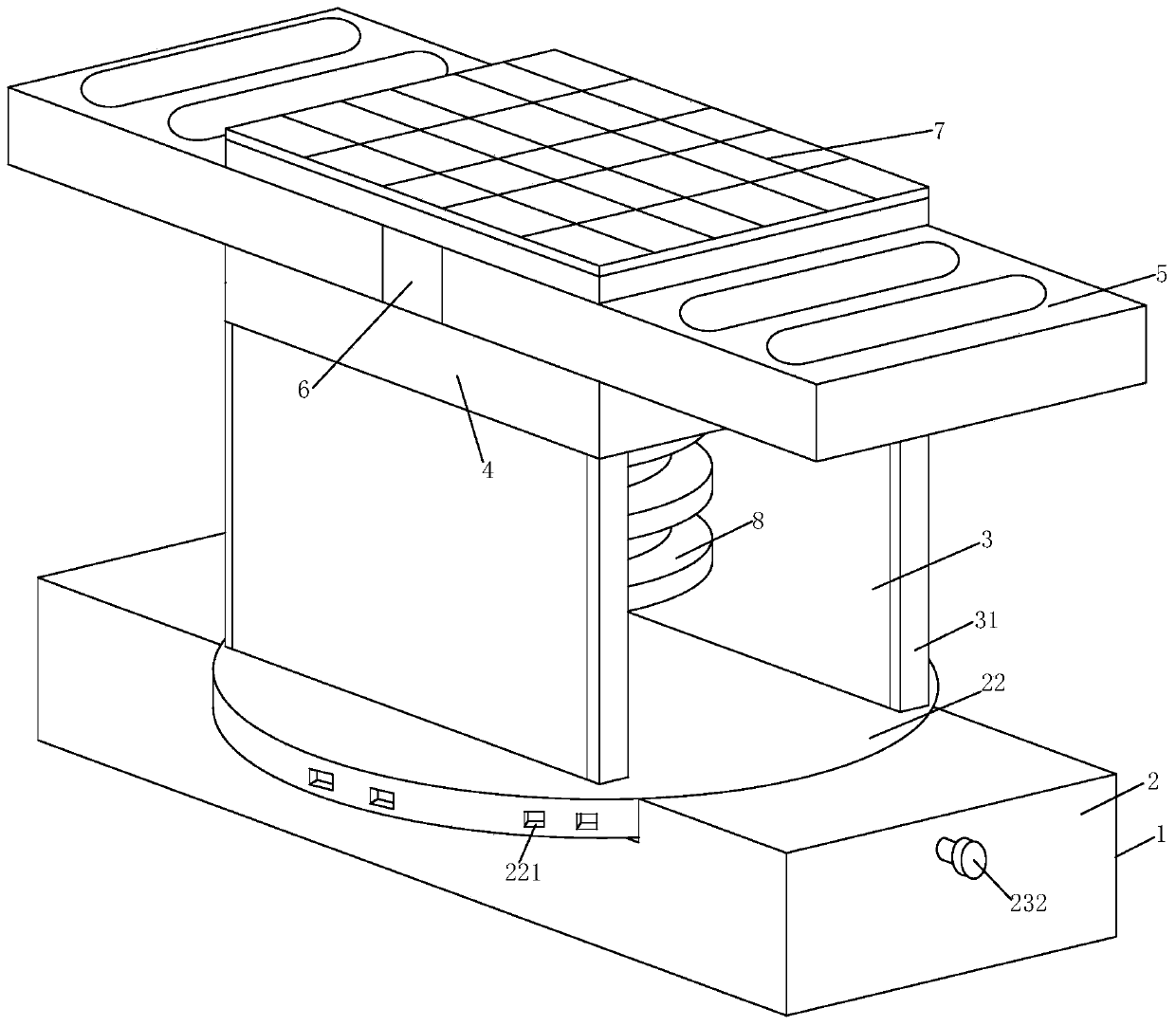
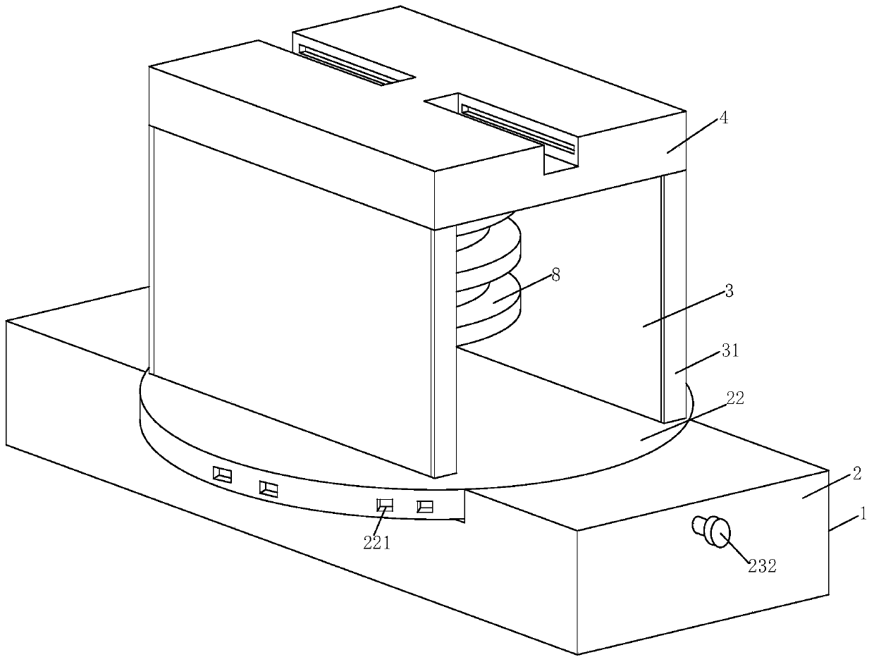
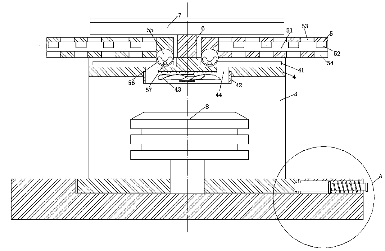
[0023] Such as Figure 1-Figure 5 As shown, a PM2.5 monitor according to the present invention includes a body 1 and a monitor 8, the body 1 includes an adjustment device 2, two support plates 3, a fixing plate 4 and two heating devices 5, the The upper surface of the adjustment device 2 is fixedly connected with the bottom of the support plate 3, the tops of the two support plates 3 are fixedly connected with the lower surface of the fixed plate 4, and the upper surface of the fixed plate 4 is connected with the lower surface of the heating device 5 Overlapping, the monitor 8 is fixedly connected to the inside of the adjustment device 2, by setting the adjustment device 2 and the fixing plate 4, the adjustment device 2 can adjust the overall ori...


PUM


Abstract

The invention relates to the field of air detection, in particular to a PM2.5 monitor. The PM2.5 monitor comprises a body and a monitor, wherein the body comprises an adjusting device, two supportingplates, a fixed plate and two heating devices, wherein the upper surface of the adjusting device is fixedly connected with the bottoms of the supporting plates; the tops of the two supporting plates are fixedly connected with the lower surface of the fixed plate respectively; the upper surface of the fixed plate is in overlap joint with the lower surface of the heating device; and the monitor is fixedly connected with the interior of the adjusting device. By arranging the adjusting device and the fixed plate, the overall orientation of the device can be adjusted by the adjusting device, the top of the monitor can be shielded by the fixed plate, the adjusting precision of the device is high due to 360-degree rotation, the problems that dust is accumulated on the surface of the monitor and the monitor is likely to be damaged caused by collision due to long-term exposure of the monitor on a construction site are solved, and the surface of the monitor can be dedusted by starting a fan, sothat the detection precision of the monitor is improved, and the applicability of the device is improved.

Description

technical field [0001] The invention relates to the field of air detection, in particular to a PM2.5 monitor. Background technique [0002] PM2.5 refers to particulate matter with an aerodynamic equivalent diameter less than or equal to 2.5 microns in the atmosphere, also known as particulate matter that can enter the lungs. Although PM2.5 is only a small component of the earth’s atmospheric composition, it has a great impact on air quality and Visibility, etc. have an important impact. PM2.5 has a small particle size, is rich in a large amount of toxic and harmful substances, and has a long residence time in the atmosphere and a long transportation distance, so it has a greater impact on human health and atmospheric environmental quality. Some PM2.5 monitors still have the following deficiencies: [0003] At present, there are hundreds of large and small construction sites under construction in the city every year. The branches are in every corner of the city. Many constru...

Claims


Application Information

Patent Timeline
Patent Type & Authority Applications(China)
IPC IPC(8): G01N15/00G01N15/06G01N1/44B08B5/02
CPCG01N15/00G01N15/06G01N1/44B08B5/02Y02A50/20
Inventor 朱增秀董军辉杨烨
Owner 河北球境环保科技有限公司
Learn More