Furnace top sealing structure of suspended type heat treatment furnace

A heat treatment furnace and sealing structure technology, applied in the direction of furnace crown/roof, furnace, furnace components, etc., can solve the problems of poor temperature uniformity in the furnace cavity, decreased reliability of the production line, easy failure of lubricating oil and electric control systems, etc. To achieve the effect of suppressing the overflow of furnace gas and smooth transition action

Pending Publication Date: 2019-12-24
天津鼎元热工工程有限公司
View PDF0 Cites 0 Cited by
  • Summary
  • Abstract
  • Description
  • Claims
  • Application Information

AI Technical Summary

Problems solved by technology

[0004] However, the problem brought by this solution is that the furnace gas flowing upward in the furnace will overflow outward along the gap between the long slot and the suspender, resulting in poor temperature uniformity in the furnace chamber and high energy consumption. At the same time, The overflow of a large amount of furnace gas caused the working environment temperature of the accumulation conveyor chain system directly above the long seam to be too high. If it is used at a temperature above 100 degrees for a long time, the lubricating oil and the electric control system are prone to failure, resulting in a decrease in the reliability of the production line.

Method used


Image

  • Furnace top sealing structure of suspended type heat treatment furnace
  • Furnace top sealing structure of suspended type heat treatment furnace
  • Furnace top sealing structure of suspended type heat treatment furnace

Examples


Embodiment Construction

[0018] The roof sealing structure of the suspension heat treatment furnace provided by the present invention will be described in detail below in conjunction with the accompanying drawings and specific embodiments.

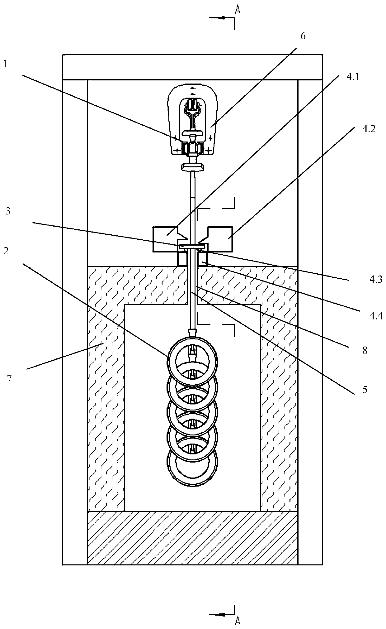
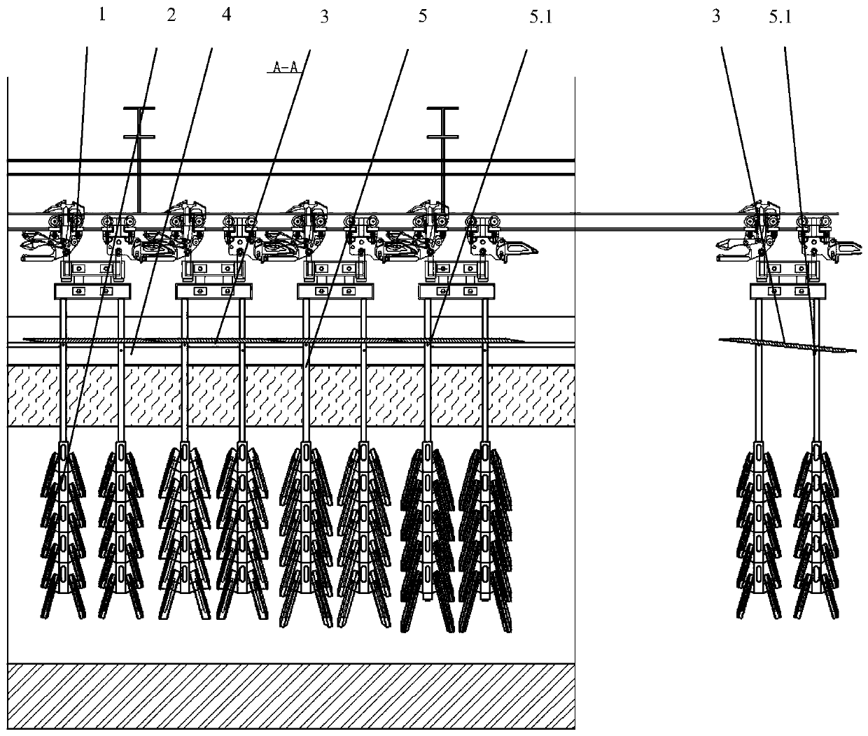
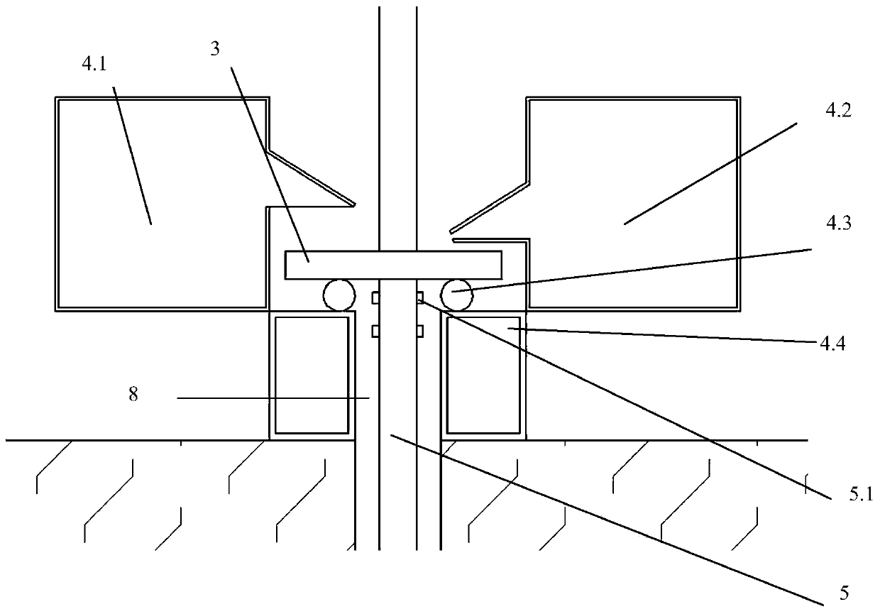
[0019] Such as figure 1 — Figure 5 As shown, the suspended heat treatment furnace in the roof sealing structure of the suspended heat treatment furnace provided by the present invention mainly includes a circulating accumulation trolley track 6, multiple accumulation trolleys 1, a furnace body 7, at least one suspender 5 and A positioning tail rod 9; multiple groups of accumulating trolleys 1 are arranged on the circular accumulating trolley track 6 in a manner that can move along the circulating accumulating trolley track 6; At a certain part, a long seam 8 is formed in the middle of the top surface along the moving direction of the accumulating trolley 1; the upper ends of multiple suspenders 5 or one suspender 5 and a positioning tail bar 9 are connected to a...


PUM


Abstract

Provided is a furnace top sealing structure of a suspended type heat treatment furnace. The furnace top sealing structure comprises a floating type cowl flap, a cooling beam and positioning pins. Thecooling beam comprises a wind gathering beam, a duckbill wind spraying beam, rails and hollow beams. The sufficient linearity can be kept during work at the room temperature and the high temperature.The floating type cowl flap serves as a cover plate and is pulled by the dead weight to move on the rails with the sufficient linearity, and the aim of retraining furnace gas from overflowing is realized. Meanwhile, a wind curtain is arranged at the upper portion of the floating type cowl flap, and therefore a small amount of overflowing furnace gas is isolated, and it is ensured that the workingtemperature of parts accumulated and conveyed on the upper side of the floating type cowl flap is close to the environment temperature all the time. Considering that the floating type cowl flap is notsupported by rails outside the furnace, the positioning pins are arranged on hanging rods. By setting the proper positions of the positioning pins, the front end of the floating type cowl flap is ina pitching state outside the furnace, and therefore it can be ensured that the transition action of the weight of the floating type cowl flap from the positioning pins to the rails is smooth when workpieces enter or leave the furnace.

Description

technical field [0001] The invention belongs to the technical field of heat treatment equipment, in particular to a top sealing structure of a suspension heat treatment furnace. Background technique [0002] At present, the heat treatment of some parts, especially the workpieces with a single variety in large quantities and whose shape is suitable for hanging, generally uses a hanging heat treatment furnace as the heat treatment equipment. Because the suspension heat treatment furnace has the advantages of large production capacity, small heating deformation of the workpiece, and reliable operation, it has been widely used in industries such as automobiles, railways, construction machinery, and military industries. However, unlike other heat treatment furnaces, a long slot must be provided on the top of the furnace body in the suspension type heat treatment furnace, for the boom connected between the accumulating trolley and the workpiece above the furnace body to move step-...

Claims


Application Information

Patent Timeline
IPC IPC(8): F27D1/02
CPCF27D1/021
Inventor 隋轶
Owner 天津鼎元热工工程有限公司
Why Eureka
Try Eureka