Grading speed obstruction algorithm-based mobile robot obstacle-avoiding method
A mobile robot, speed obstacle technology, applied in the direction of instruments, non-electric variable control, two-dimensional position/channel control, etc. Obstacle trajectory and the situation when the algorithm has no solution, the effect of reducing the amount of calculation and saving the amount of calculation
- Summary
- Abstract
- Description
- Claims
- Application Information
AI Technical Summary
Problems solved by technology
Method used
Image
Examples
Embodiment 1
[0063] The parameters involved in the simulation of Embodiment 1 are shown in Table 1 and Table 2.
[0064] Table 1 Robot physical constraints
[0065]
[0066] Table 2 Algorithm parameters
[0067]
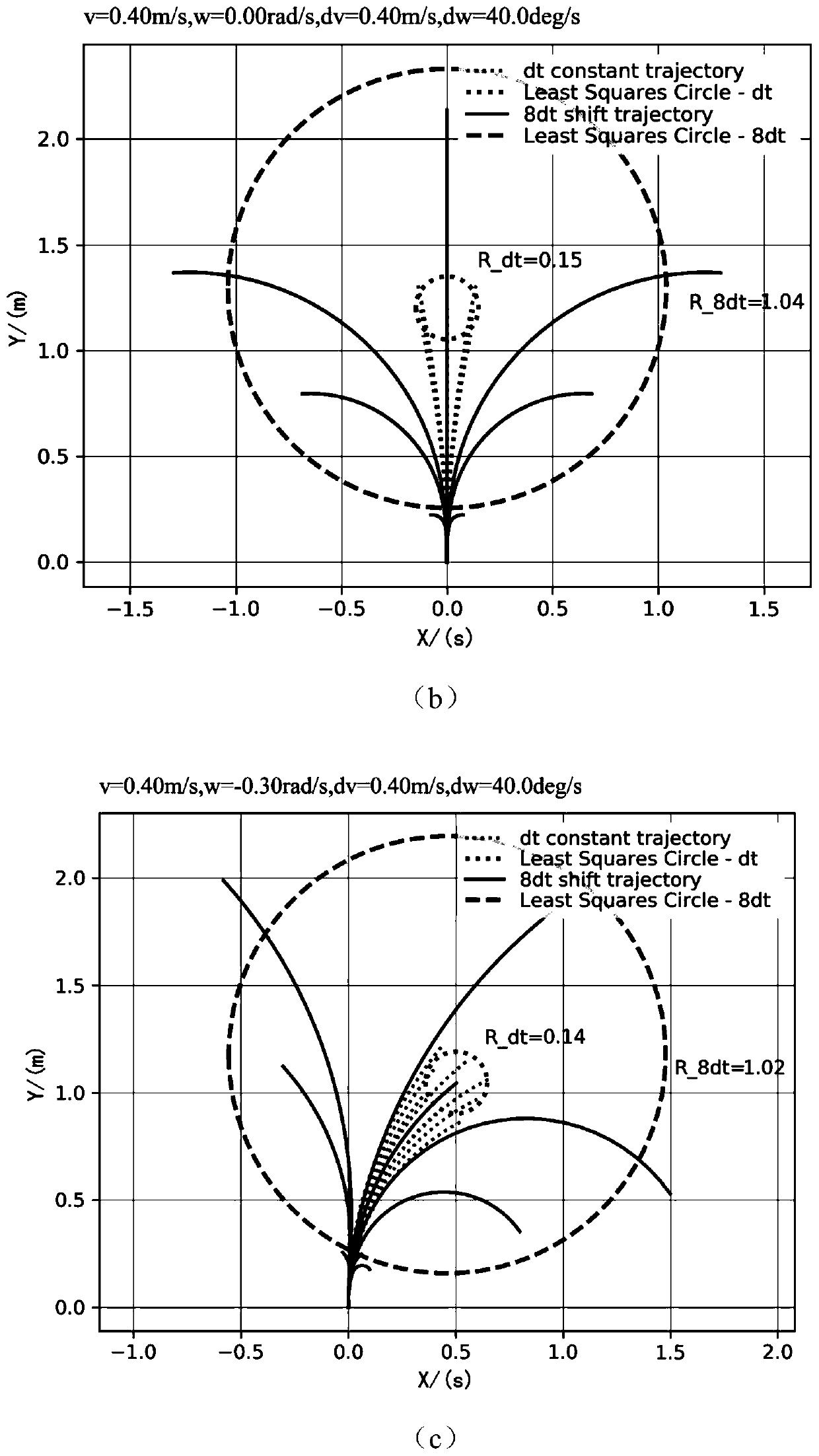
[0068] figure 2 is a one-step reachable control set U dt The generated uniform trajectory and the multi-step reachable control set U 8dt The distribution of the generated variable speed trajectory is compared, figure 2 (a) is the case of ω figure 2 (b) is the case of ω=0, figure 2 (c) is the case of ω>0. One-step reachable control set U dt The radius of the fitting circle at the end point of the uniform velocity trajectory is 0.14-0.15m. Multi-step reachable control set U 8dt The speed-changing trajectory consists of 8 sampling times of variable-speed motion and uniform motion after reaching multi-step reachable control. The maximum acceleration is used to approach multi-step reachable control at each moment in the first 8 sampling times. The radius of the fitting ...
Embodiment 2
[0078] The parameters involved in the simulation of Embodiment 2 are shown in Table 1 and Table 2.
[0079] Table 4 Robot and obstacle state
[0080] Numbering x / (m) y / (m) θ / (deg) v / (m / s) ω / (rad / s) robot 1 -1.0 -1.0 45 1.0 0.0 robot 2 11.0 -0.5 180 0.8 0.0 robot 3 -2.0 6.0 0.0 0.7 0.0 obstacle 1 6.0 5.0 180 0.8 0.2 obstacle 2 10.0 10.0 -135 1.0 0.25
[0081] Figure 8 This is the simulation effect diagram of the robot obstacle avoidance when the robot and the obstacle coexist in the invention embodiment 2. In the figure, the robot reaches different target points respectively, the starting point is marked by a cross, and the end point is marked by a five-pointed star. The robot and the dynamic obstacle start to move with the initial state shown in Table 4. The target point of robot 1 is (8,9), the target point of robot 2 is (2,5), and the target point of robot 3 is (10,0). During the obstacle avoidance ...
Embodiment 3
[0085] The parameters involved in the simulation of Embodiment 3 are shown in Table 1 and Table 2.
PUM
 Abstract
Description
Claims
Application Information
 - Generate Ideas
- Intellectual Property
- Life Sciences
- Materials
- Tech Scout
- Unparalleled Data Quality
- Higher Quality Content
- 60% Fewer Hallucinations
Browse by: Latest US Patents, China's latest patents, Technical Efficacy Thesaurus, Application Domain, Technology Topic, Popular Technical Reports.
© 2025 PatSnap. All rights reserved.Legal|Privacy policy|Modern Slavery Act Transparency Statement|Sitemap|About US| Contact US: help@patsnap.com


