
Broadband cavity enhanced apparatus

A technology of intensifying devices and broadband cavities, applied in measuring devices, material analysis through optical means, instruments, etc., can solve problems such as complex components and inability to obtain fine features of overlapping spectra, and achieve improved resolution, compact structure, small size effect

Pending Publication Date: 2019-12-20
HEFEI INSTITUTES OF PHYSICAL SCIENCE - CHINESE ACAD OF SCI
View PDF9 Cites 1 Cited by
  • Summary
  • Abstract
  • Description
  • Claims
  • Application Information

AI Technical Summary

Problems solved by technology

Although this kind of monitoring system can obtain higher detection sensitivity, there is only one-dimensional dispersion spectrum that can be output by it because the spectrometer as the detector uses grating spectrometer and the light-receiving device is a one-dimensional linear array CCD target surface. At the same time, the information can be reversed for a few gas components such as nitrogen dioxide gas and glyoxal gas. However, the components of the atmosphere are very complex, and the absorption spectrum structures of each component overlap, so it is impossible to obtain the fine details of these overlapping spectra. lack of features

Method used


Image

  • Broadband cavity enhanced apparatus
  • Broadband cavity enhanced apparatus
  • Broadband cavity enhanced apparatus

Examples


Embodiment Construction

[0031] The preferred modes of the present invention will be further described in detail below in conjunction with the accompanying drawings.

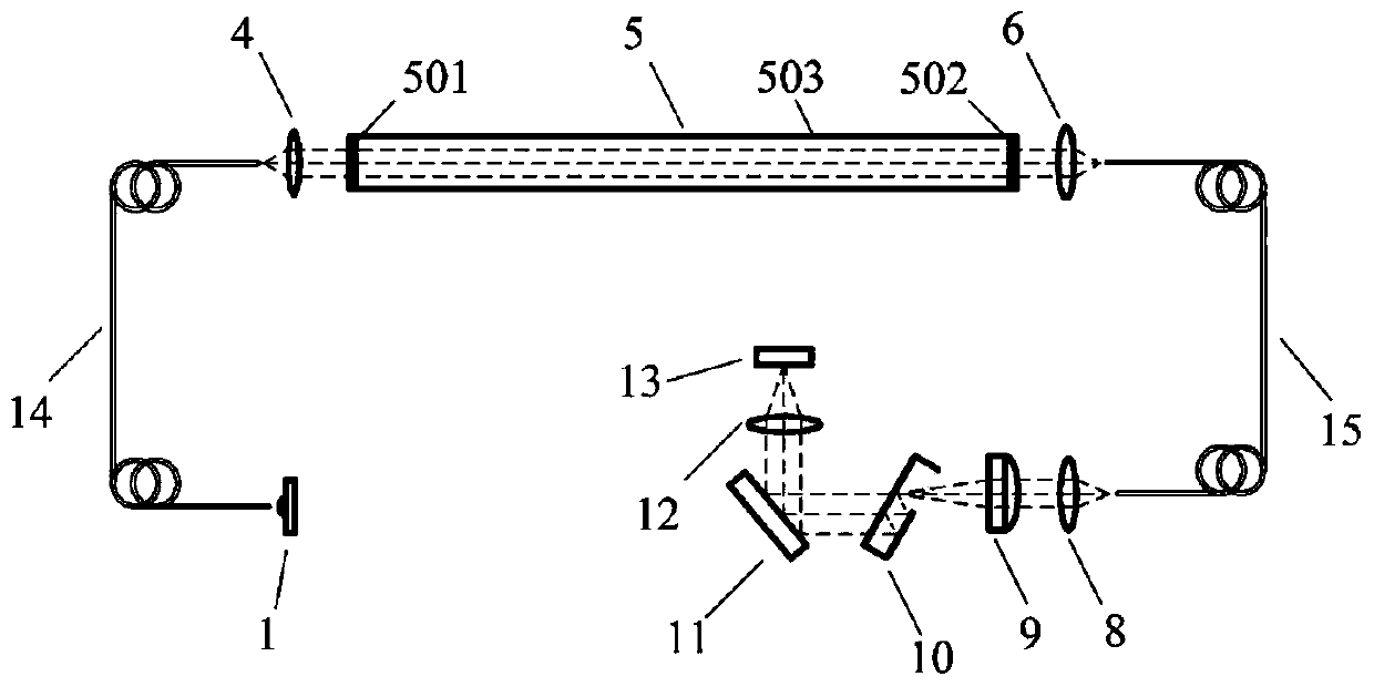
[0032] see figure 1 , figure 2 , image 3 and Figure 4 , the composition of the broadband cavity enhancement device is as follows:

[0033] On the optical path of the broadband light source 1 as a radiation source, an optical coupler 20, an optical resonant cavity 5 as a broadband enhancement cavity, a collimator 21 as a filtering and converging device, a cylindrical lens 9 and a detector are arranged in sequence; wherein:

[0034] The broadband light source 1 is a broadband laser source (it can also be a broadband LED light source, or a blackbody radiation source, or a broadband light source), which is now selected as a broadband laser frequency comb—a broadband femtosecond pulse laser source.

[0035] The optical coupler 20 is the first focusing lens 2, the first spatial filter 3 and the coupling lens 4 optically connected in se...


PUM

PropertyMeasurementUnit
reflectanceaaaaaaaaaa

Abstract

The present invention discloses a broadband cavity enhanced apparatus. The apparatus comprises a broadband light source (1), an optical resonator (5), a collimation part (21), a cylindrical lens (9) and a detector that are optically connected. The detector is a flat etalon (10), a blazed grating (11), an imaging lens (12) and a CCD target surface (13) that are successively optically connected. Anincluded angle between the flat etalon (10) and an optical axis output by the collimation part (21) is 1 to 20 degrees. Further, a flat back surface (1003) of the flat etalon (10) is located on a focal plane of the cylindrical lens (9). A flat front surface incident window (1001) of the flat etalon (10) is coated with an antireflection film. The flat front surface (1002) and the flat back surface(1003) are coated with a reflecting film. The imaging lens (12) is located at a first-order diffraction light image of the blazed grating (11). The CCD target surface (13) is a two-dimensional area-array target surface located at an image of the imaging lens (12). The apparatus can be used for simultaneously measuring more gas components, and can be widely used for atmospheric trace and aerosol optical property measurement.

Description

technical field [0001] The invention relates to a cavity enhancement device, in particular to a broadband cavity enhancement device. Background technique [0002] Cavity-enhanced absorption spectroscopy technology has been widely used in the measurement of atmospheric trace gases and aerosol optical properties. Using a high-precision optical resonant cavity composed of high-reflection cavity mirrors, it can achieve several thousand meters on a base length of 1 meter. The effective absorption optical path significantly improves the sensitivity of measurement, such as a broadband cavity enhanced absorption spectrum atmospheric environment monitoring system announced on August 11, 2010 in Chinese invention patent CN 101281124B. The monitoring system mentioned in this patent is mainly composed of a radiation source, a converging shading device, a broadband enhancement cavity, a filter convergence device, and a detector connected in sequence. The broadband enhancement cavity is a...

Claims


Application Information

Patent Timeline
Patent Type & Authority Applications(China)
IPC IPC(8): G01N21/31G01N21/01
CPCG01N21/01G01N21/31
Inventor 方波赵卫雄张为俊
Owner HEFEI INSTITUTES OF PHYSICAL SCIENCE - CHINESE ACAD OF SCI
Learn More