Reciprocating low pressure high frequency hydraulic pulse vibrator

A hydraulic pulse and reciprocating technology, applied in vibration drilling and other directions, can solve problems such as high working pressure loss and vibration force, difficult tool face control, and large rotor torque

Active Publication Date: 2020-08-25
HELI TECH ENERGY CO LTD
View PDF5 Cites 0 Cited by
  • Summary
  • Abstract
  • Description
  • Claims
  • Application Information

AI Technical Summary

Problems solved by technology

Axial static friction leads to the ineffective transmission of bit pressure; circumferential static friction leads to discontinuous rotation of drill tools
These two phenomena create various problems for drilling operations: under pressure of the motor, damage of the drill bit, difficult control of the tool face, excessive compression of the drill tool, sticking of the drill bit, torque fluctuation, increased risk of drill tool undercut, fatigue of the drill tool, etc. The tools still have problems such as non-adjustable drilling fluid flow area and high tool pressure loss.
The disclosed technology with the application number 2018113005317 solves the above problems to a certain extent, but due to the unreasonable design of the piston structure, the working pressure loss and vibration force are relatively high; High pressure loss and easy to wear

Method used


Image

  • Reciprocating low pressure high frequency hydraulic pulse vibrator
  • Reciprocating low pressure high frequency hydraulic pulse vibrator
  • Reciprocating low pressure high frequency hydraulic pulse vibrator

Examples


Embodiment Construction

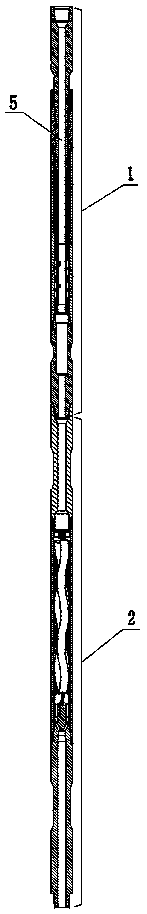
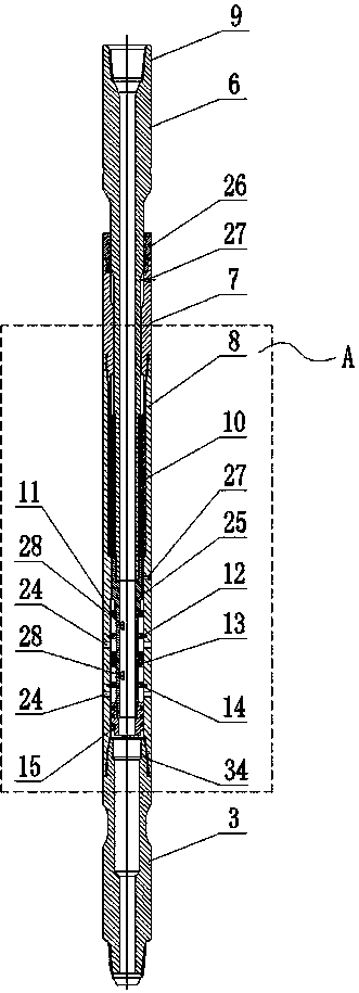
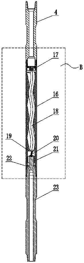
[0016] Such as Figure 1-5 As shown, the reciprocating low-pressure high-frequency hydraulic impulse vibrator of the present invention is composed of a combination of a vibrating sub-section 1 and a power sub-section 2. The vibrating sub-section 1 and the power sub-section 2 are both hollow and tubular, and the vibrating sub-section 1 passes The lower joint 3 underneath is threadedly connected with the upper joint 4 above the power nipple 2, so that a pulse channel 5 is formed between the vibrating nipple 1 and the power nipple 2. Specifically, the spline core shaft 6, the spline outer cylinder 7, the piston inner cylinder 25, the piston outer cylinder 8, the lower joint 3, the upper joint 4, the stator sleeve 16 and the bottom joint 23 are all hollow tubulars, and the pulse channel 5 It is composed of a spline mandrel 6, a piston inner cylinder 25, a lower joint 3, an upper joint 4, a stator sleeve 16, a flushing channel 21 and a bottom joint 23 connected in sequence.

[0017] ...


PUM


Abstract

The invention relates to a reciprocating type low-pressure and high-frequency hydraulic power pulse vibrator and belongs to the field of vibration or oscillation method well drilling. The reciprocating type low-pressure and high-frequency hydraulic power pulse vibrator is composed of a vibration short joint and a power short joint. The vibration short joint is formed in the manner that a spline core shaft is inserted in a spline outer cylinder and a piston outer cylinder, and a disc spring is installed in the circular clearance between the middle portion of the spline core shaft and the pistonouter cylinder. The lower end of the spline core shaft is fixedly connected with a piston inner cylinder. A piston I, a piston II and a piston III are sequentially fixed to the piston inner cylinderfrom top to bottom, and an isolation ring I and an isolation ring II are fixed to the inner surfaces of the parts, between the piston II and the piston II and between the piston II and the piston III,of the piston outer cylinder correspondingly. A spiral worm is arranged in a stator sleeve in the axial direction, the lower end of the spiral worm abuts against a disc support, and a connecting rodhinged to the lower end face of the spiral worm is hinged to the center position of the upper end of a vibrator valve cone which is arranged in the stator sleeve in a clearance fit manner. By means ofthe reciprocating type low-pressure and high-frequency hydraulic power pulse vibrator, the pressure loss of the tool can be reduced by 45%, and meanwhile the problems of motor backing pressure, drillhead damage, drilling tool clamping, torque fluctuation, drilling tool fatigue and the like are solved.

Description

Technical field [0001] The invention relates to the field of drilling using vibration or oscillation methods, in particular to a reciprocating low-pressure high-frequency hydraulic impulse vibrator. Background technique [0002] The static friction between the drilling tool and the borehole wall has brought great challenges to the drilling of directional and horizontal wells. According to the direction, this static friction can be divided into two categories: one is the axial friction generated during sliding drilling, and the other is the circumferential friction generated during rotary drilling. Axial static friction results in the ineffective transmission of WOB; circumferential static friction causes discontinuous rotation of the drill tool. These two phenomena create various problems for drilling operations: motor back pressure, drill bit damage, tool face difficult to control, excessive drilling tool compression, stuck drilling, torque fluctuations, increased risk of drill...

Claims


Application Information

Patent Timeline
Patent Type & Authority Patents(China)
IPC IPC(8): E21B7/24
CPCE21B7/24
Inventor 侯立东
Owner HELI TECH ENERGY CO LTD
Why Eureka
Try Eureka