
Novel prefabricated type building thermal-insulation block system and assembly method thereof

A technology for building thermal insulation and thermal insulation blocks, which is applied in construction, building materials, building components, etc., can solve the problems of increasing cold bridges, easy disintegration of composite self-insulating blocks, and increased costs.

Inactive Publication Date: 2019-12-20
HENAN XIAN NEW BUILDING MATERIALS
View PDF5 Cites 0 Cited by
  • Summary
  • Abstract
  • Description
  • Claims
  • Application Information

AI Technical Summary

Problems solved by technology

[0002] At present, the domestic building insulation layer is mainly based on the external thermal insulation construction method, supplemented by the internal thermal insulation construction method. It is more common to use the prefabricated building thermal insulation block method for the internal thermal insulation construction method, but although the existing building thermal insulation blocks use broken The bridge composite self-insulation blocks are built into the wall, but because the composite self-insulation blocks of the broken bridge are prevented from being multi-oriented, the concrete block body of the composite self-insulation block of the broken bridge is distributed in disorder on the heat insulation material The elimination of the cold bridge phenomenon cannot be guaranteed or there is an increase in the cold bridge phenomenon
Secondly, EPS (polystyrene foam) is used to clamp between two layers of blocks. Since there is no self-bonding function between EPS and blocks, the composite self-insulating blocks are easy to disintegrate. Adhesives instead of EPS materials will increase the cost of manufacturing with the improvement of bonding conditions, and the economy is poor

Method used


Image

  • Novel prefabricated type building thermal-insulation block system and assembly method thereof
  • Novel prefabricated type building thermal-insulation block system and assembly method thereof
  • Novel prefabricated type building thermal-insulation block system and assembly method thereof

Examples


Embodiment Construction

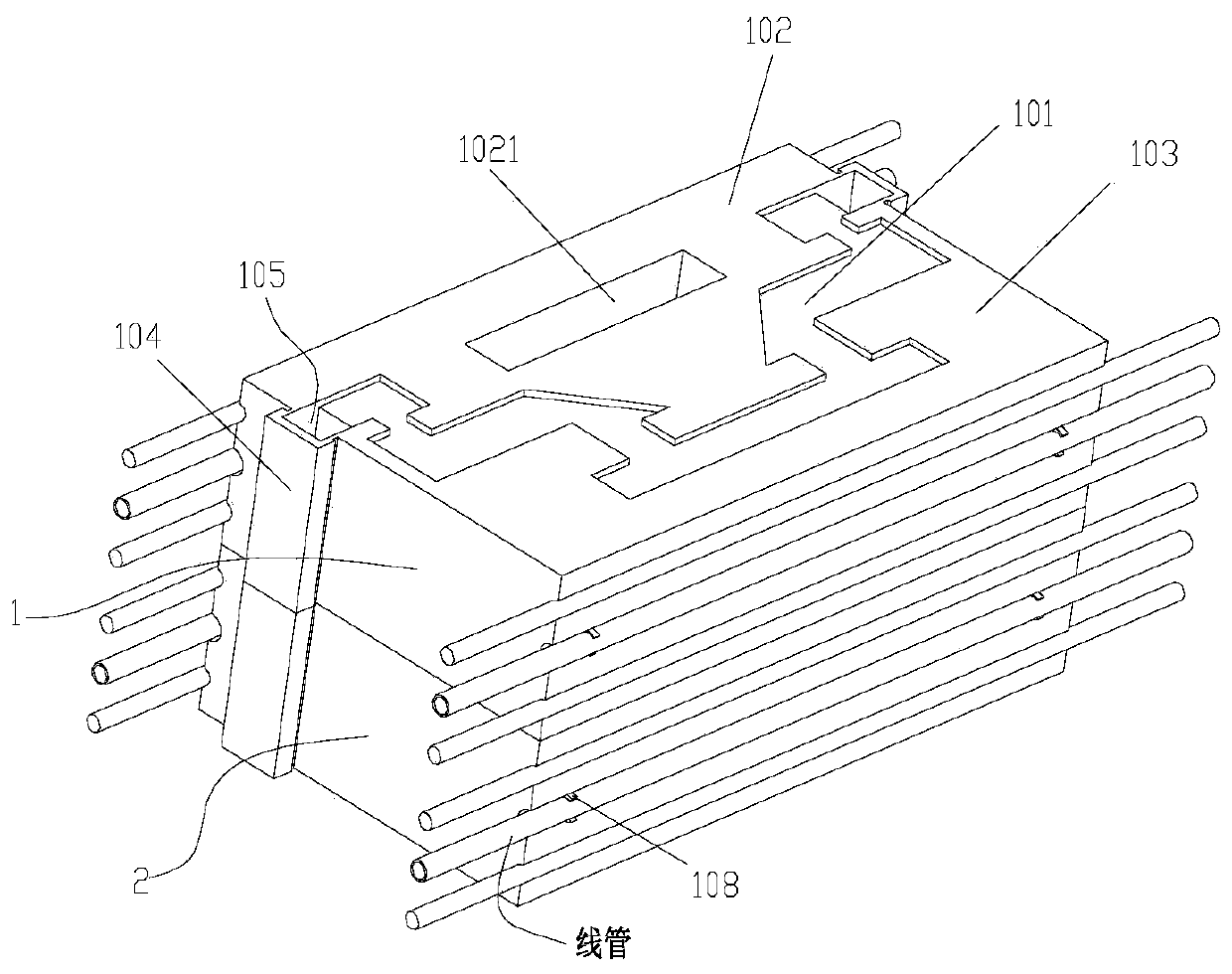
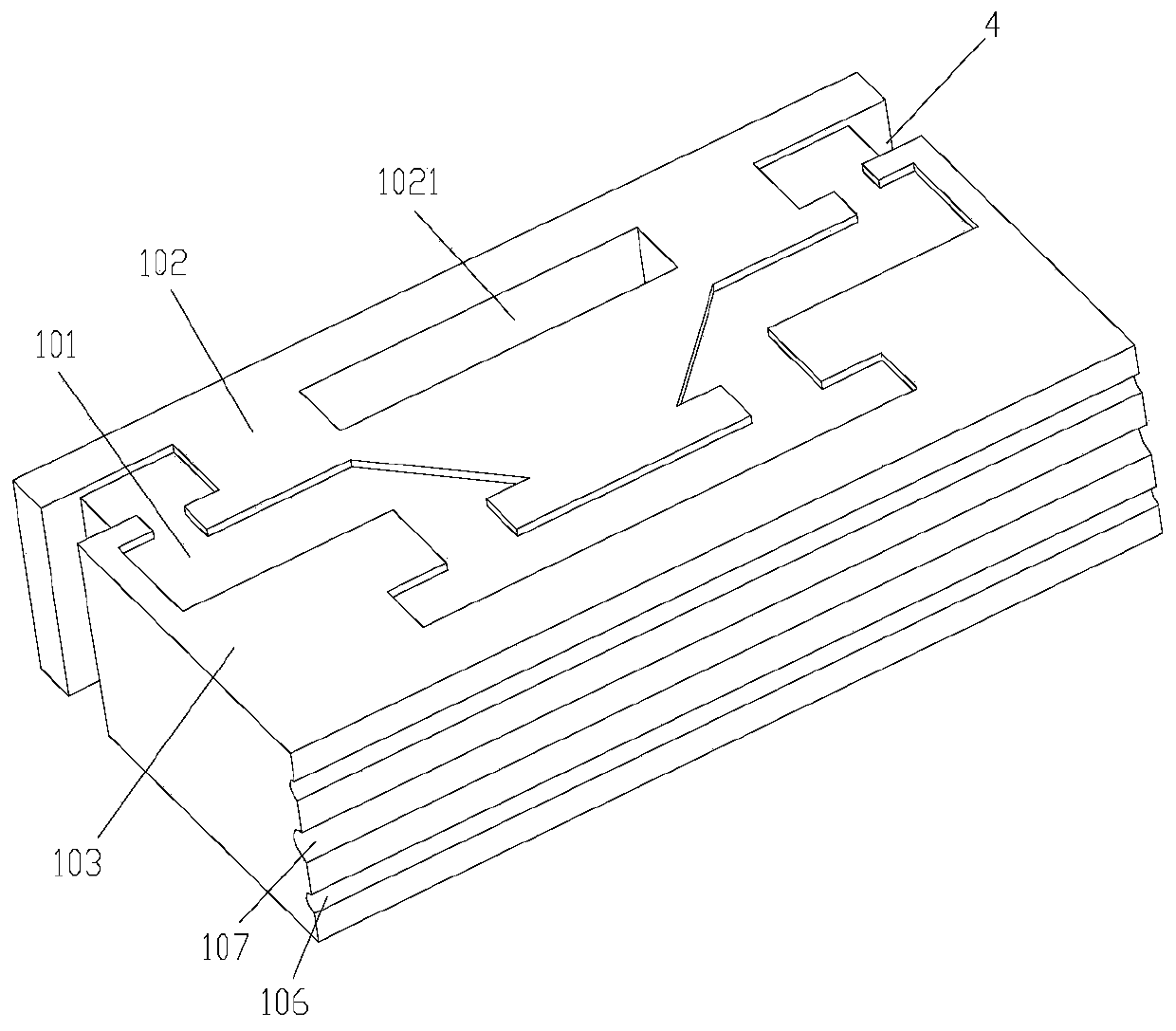
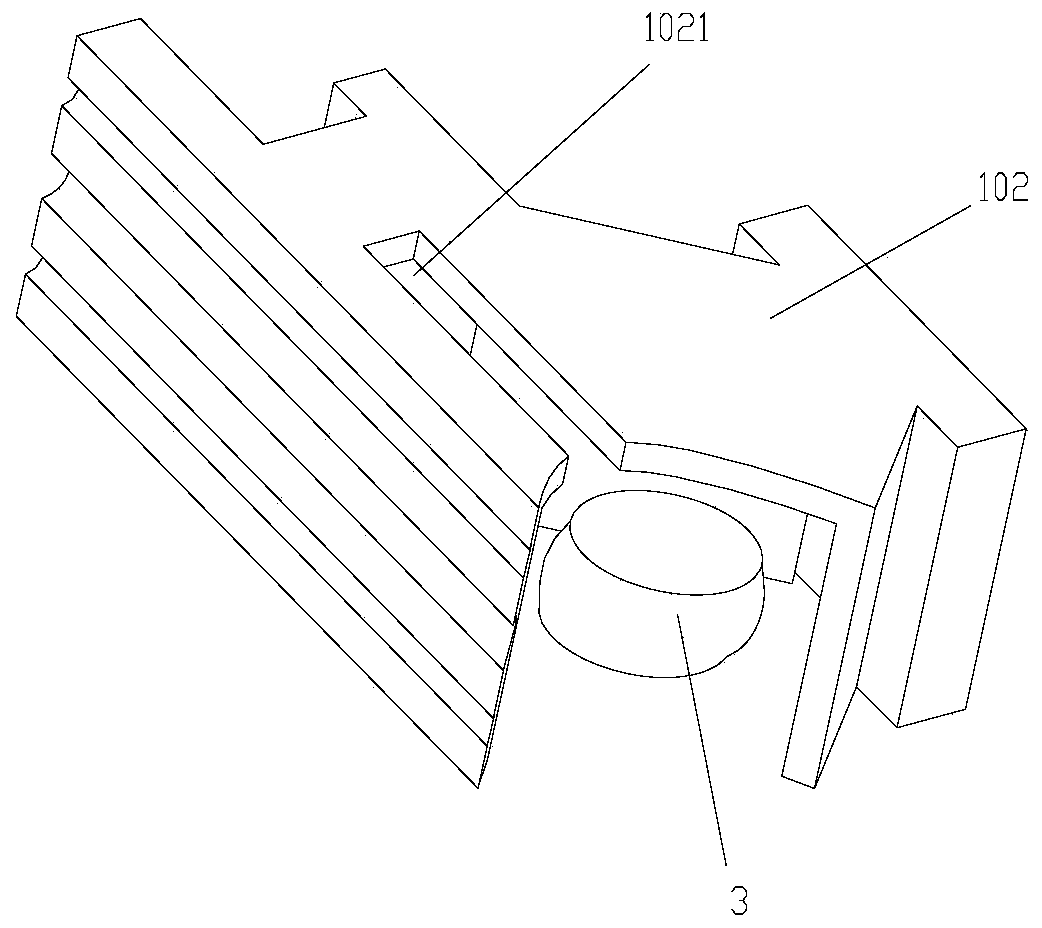
[0023] As shown in the figure: a new type of prefabricated building thermal insulation block system according to the present invention includes a composite thermal insulation block and a steel cage for enhancing the stability of the thermal insulation block after laying. block 1 and lower block 2, the upper block 1 and the lower block 2 form a symmetrical structure, the lower part of the upper block 1 is provided with a cavity for filling the vacuum bag 3, and the upper end of the upper block 1 is provided with a The steps in the front and rear direction have a step ESP insulation layer 101, and the end faces of the outwardly extending ends of the step ESP insulation layer 101 are indented inwardly with a distance of 5-10cm left on the outer side of the upper block 1 to form a reserved groove 4 and will The upper block is divided into a front block 103 and a rear block 102, the cavities are all located inside the rear block 102, and the reserved groove 4 is filled with slurry o...


PUM


Abstract

The invention discloses a novel prefabricated type building thermal-insulation block system. The system comprises a composite thermal-insulation block and a steel reinforcement cage used for enhancingstability of the composite thermal-insulation block after construction, wherein the composite thermal-insulation block comprises an upper block and a lower block, the upper block and the lower blockare in symmetric structures, a cavity used for filling a vacuum bag is arranged at the lower part of the upper block, a step ESP thermal-insulation layer in the front-back direction is arranged at theupper end of the upper block, the end surface of the outward extending end of the step ESP thermal-insulation layer is retracted inwards to form a distance of 5-10 cm to the outer side surface of theupper block, therefore a preformed groove is formed and divides the upper block into a front block and a rear block, the overall cavity is located in the rear block, and the preformed groove is filled with slurry of a thermal insulation material. The system is good in thermal-insulation effect and high in assembly efficiency and the construction is convenient and fast.

Description

technical field [0001] The invention relates to a thermal insulation block system, in particular to a new prefabricated building thermal insulation block system and an assembly method thereof. Background technique [0002] At present, the domestic building insulation layer is mainly based on the external thermal insulation construction method, supplemented by the internal thermal insulation construction method. It is more common to use the prefabricated building thermal insulation block method for the internal thermal insulation construction method, but although the existing building thermal insulation blocks use broken The bridge composite self-insulation blocks are built into the wall, but because the composite self-insulation blocks of the broken bridge are prevented from being multi-oriented, the concrete block body of the composite self-insulation block of the broken bridge is distributed in disorder on the heat insulation material On the other hand, the elimination of ...

Claims


Application Information

Patent Timeline
IPC IPC(8): E04C1/00E04C1/39E04C1/41
CPCE04C1/00E04C1/397E04C1/41
Inventor 司政凯张梦张梦安陈晓飞赵明伟王巍李宁刘光武刘燕刚曹林方
Owner HENAN XIAN NEW BUILDING MATERIALS
Learn More