Double-turntable spring type arc extinguishing lightning protection device
A lightning protection device and spring-type technology, which is applied to overvoltage arresters, electrical components, spark gaps, etc., which use spark gaps, can solve problems affecting arc extinguishing, large friction between arc extinguishing cylinders and gas pill disks, etc., and achieve Increased loading capacity, low cost, and easy to achieve effects
- Summary
- Abstract
- Description
- Claims
- Application Information
AI Technical Summary
Problems solved by technology
Method used
Image
Examples
Embodiment 1
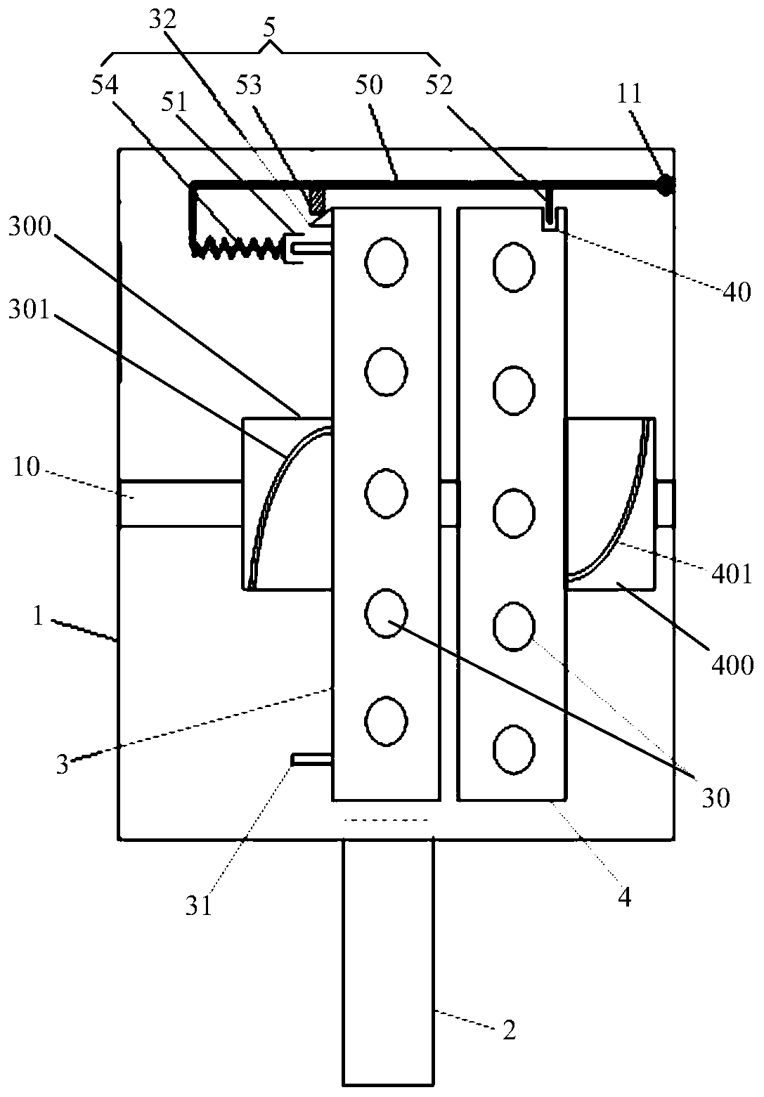
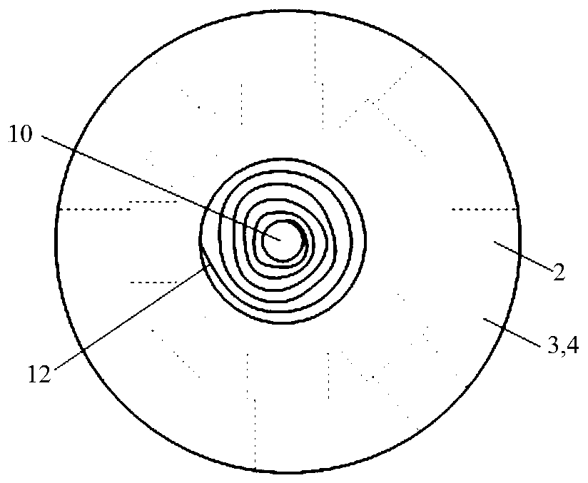
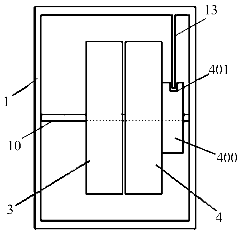
[0027] Such as figure 1 , figure 2 , image 3 and Figure 4As shown, according to a double-disk clockwork type arc extinguishing and lightning protection device of the present invention, the arc extinguishing and lightning protection device includes an arc extinguishing and lightning protection housing 1, an arc extinguishing cylinder 2, A rotary disc 3 and B rotary disc 4 and a drive The switching device 5 is horizontally provided with a rotatable central shaft 10 in the arc extinguishing and lightning protection housing 1, the A rotary table 3 and the B rotary table 4 are slidably arranged on the central shaft 10, and the A rotary table 3 and the B rotary table The circumferential side wall of 4 is uniformly provided with a plurality of placement grooves 30 for placing gas pills in the radial direction, and a gas pill trigger position is provided on the lower side wall of the arc extinguishing and lightning protection shell 1, and the arc extinguishing The cylinder 2 is ...
Embodiment 2
[0031] The difference between the second embodiment and the first embodiment is that only the B sleeve 400 is fixedly sleeved on the central axis 10, such as Figure 4 As shown, the A turntable 3 is directly slidably arranged on the central shaft 10, and the spiral slide rail 301 may or may not be provided directly on the central shaft 10, and the B turntable 4 is slidably arranged on the B sleeve 400, and the B turntable 4 Set the central shaft 10 through the B sleeve 400, and set a spiral slide rail 401 on the outer wall of the B sleeve 400, and the B turntable 4 is sleeved on the outer wall of the B sleeve 400 through the spiral slide rail 401 , when the B turntable 4 rotates with the central axis 10 and can slide along the spiral slide rail 401, the outer circumferences of the A turntable 3 and B turntable 4 are on the same horizontal line and the outer diameters of the two disks are the same, and A The turntable 3 and the B turntable 4 are rotatably installed in the arc e...
Embodiment 3
[0033] The difference between the third embodiment and the first embodiment is that in the present invention, the combination figure 1 , Figure 6 and Figure 8 The protruding ring 302 is used to replace the annular convex rail 31, and the protruding ring 302 is provided on the edge of the A turntable 3 and away from the side of the B turntable 4, that is, the convex ring 302 is arranged on the left edge of the A turntable 3. Ring 302, the convex ring 302 is rigid or elastic, and the short side end of the L-shaped rotating rod 50 is sequentially connected to the convex ring 302 provided on the A rotary disk 3 through the compression spring 54, the sleeve cap 51; The protruding ring 302 is provided with a recessed point 303, and the recessed point 303 is arranged near the placement groove 30 for placing the gas pellets that is finally triggered on the A turntable 3. When the last gas shot in the placement groove 30 of the A turntable 3 After the pill is triggered, the concave...
PUM
 Abstract
Description
Claims
Application Information
 - R&D
- Intellectual Property
- Life Sciences
- Materials
- Tech Scout
- Unparalleled Data Quality
- Higher Quality Content
- 60% Fewer Hallucinations
Browse by: Latest US Patents, China's latest patents, Technical Efficacy Thesaurus, Application Domain, Technology Topic, Popular Technical Reports.
© 2025 PatSnap. All rights reserved.Legal|Privacy policy|Modern Slavery Act Transparency Statement|Sitemap|About US| Contact US: help@patsnap.com


