
Method for controlling double UAVs (unmanned aerial vehicles) to cooperatively hoist rod-shaped rigid load

A technology of dual UAVs and control methods, applied in general control systems, adaptive control, control/regulation systems, etc., can solve the problems of inability to fully apply UAV systems, difficulties in experimental verification, and a large number of variables. Good practical application significance, good load swing, and the effect of load swing suppression

Active Publication Date: 2019-12-17
NANKAI UNIV
View PDF3 Cites 11 Cited by
  • Summary
  • Abstract
  • Description
  • Claims
  • Application Information

AI Technical Summary

Problems solved by technology

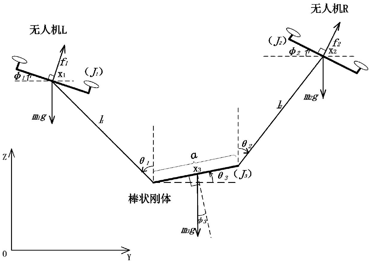
[0004] Scholars in related fields at home and abroad have also made corresponding research on the multi-UAV collaborative lifting problem. The specific solution to the problem is divided into two steps. The first is to establish a complete and accurate system dynamics model. This is the next step. Based on the analysis, some scholars have done a lot of work on system dynamics analysis [3-5]. [6-8], but the application of this Lagrangian modeling method in multi-UAV cooperative work is extremely complex, and the number of variables involved is large, so it is difficult to calculate, and the specific experimental verification is relatively difficult. Difficult, many research results only give simulation verification[9-10]
For the proposed dual-UAV collaborative lifting system, the model can be established in two-dimensional or three-dimensional space according to the characteristics of the load. The dynamic modeling in two-dimensional space can refer to some plane modeling methods such as cranes. Lu et al. The motion state of the two cranes is analyzed in the plane and a collaborative work method is proposed [11], but in comparison, the height of the UAV is not completely fixed, and this method cannot be fully applied to the UAV system

Method used


Image

  • Method for controlling double UAVs (unmanned aerial vehicles) to cooperatively hoist rod-shaped rigid load
  • Method for controlling double UAVs (unmanned aerial vehicles) to cooperatively hoist rod-shaped rigid load
  • Method for controlling double UAVs (unmanned aerial vehicles) to cooperatively hoist rod-shaped rigid load

Examples


Embodiment 1

[0050] 1. Dynamic modeling of dual-UAV collaborative lifting system:

[0051]

[0052]

[0053]

[0054]

[0055]

[0056] Here, the selected system parameters are as follows:

[0057] m 1 = m 2 =3kg,m 3 =20kg,J 1 =J 2 =7kg·m 2 , l 1 = l 2 =2m, a=5m, g=9.8m / s 2

[0058] 2. Design of UAV outer loop controller

[0059] By deriving the outer loop Lyapunov function (21), the control input structure can be designed as follows:

[0060]

[0061]

[0062]

[0063]

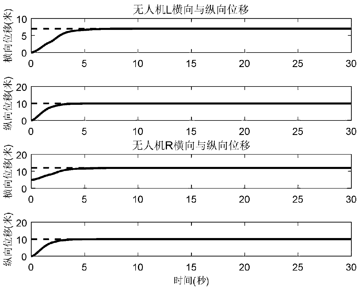
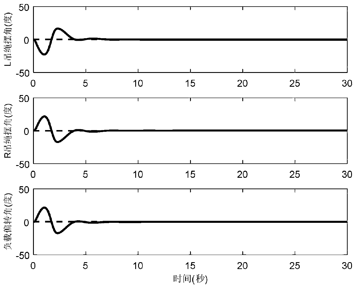
[0064] Among them, the expected positions of the two UAVs are set as [y d1 z d1 ] T =[7 10] T ,[y d2 z d2 ] T =[1210] T , and the expected angles of rope swing angle and load swing angle are θ 1d = θ 2d = θ 3d = 0°. k a1 ,k a2 ,k d1 ,k d2 ,k d3 ,k d4 is a positive control gain, using the control inputs (23) and (24) designed by the outer loop controller, it can realize the fixed-point hovering of the drone, eliminate the load swing and control the distance between t...


PUM


Abstract

The invention discloses a method for controlling double UAVs to cooperatively hoist a rod-shaped rigid load, and provides the modeling and control method aimed at a double UAV cooperative hoisting system in a plane. A complete system dynamic model is established by using a Lagrange modeling method, and the relative kinematic relationship between the two rotor UAVs and a load is analyzed. On the basis of the established model, a Lyapunov method is used for designing a controller, an outer loop stability analysis is carried out by combining a Lassalle invariance principle, and then a conclusionthat an expected balance point is asymptotically stable is obtained. According to the control scheme, the UAVs can be prevented from colliding with each other, a hoisting task is stably completed, fixed-point hovering is achieved, and swinging of the load is inhibited. According to an experiment result, the control objective can be completed, the two UAV are ensured to fly with respective expectedranges, and load swinging can be effectively inhibited.

Description

technical field [0001] The invention belongs to the technical field of automatic control of nonlinear underactuated electromechanical systems, and in particular relates to a modeling and control method for cooperative lifting of two unmanned aerial vehicles. Background technique [0002] UAV transportation is a transportation method in which the items to be transported are automatically delivered to the destination according to the planned route by lifting or clamping. Solve the distribution problem in remote areas, and the transportation efficiency is high. [0003] The purpose of multi-UAV collaborative lifting of heavy loads is to use general lifting devices to solve special delivery tasks, such as handling large cargo, or have special requirements for the attitude of the load during the lifting process. The rotor UAV itself is a type of underactuated system, and when it lifts the load, the entire lifting system becomes a double underactuated system, and it is a major di...

Claims


Application Information

Patent Timeline
IPC IPC(8): G05B13/04
CPCG05B13/042
Inventor 方勇纯张鹏梁潇
Owner NANKAI UNIV
Learn More