
Depth sensor calibration system and method

A depth sensor and calibration system technology, applied in the field of depth sensors, can solve the problems of test environment, signal strength test accuracy limitation, etc., and achieve the effect of improving performance and calibration accuracy

Pending Publication Date: 2019-12-17
BENEWAKE BEIJING TECH CO LTD
View PDF7 Cites 4 Cited by
  • Summary
  • Abstract
  • Description
  • Claims
  • Application Information

AI Technical Summary

Problems solved by technology

[0006] Currently known calibration methods can calibrate the sensor by adjusting the position of the measured object and / or the depth sensor to change the distance between the measured object and the depth sensor, but this calibration method has limitations in the test environment, signal strength, and test accuracy and other restrictions

Method used


Image

  • Depth sensor calibration system and method
  • Depth sensor calibration system and method
  • Depth sensor calibration system and method

Examples


Embodiment Construction

[0042] In order to better understand the above technical solutions, the technical solutions of the embodiments of this specification will be described in detail below through the drawings and specific examples. It should be understood that the embodiments of this specification and the specific features in the embodiments are the technical solutions of the embodiments of this specification. It is a detailed description, rather than a limitation to the technical solutions of this specification. In the case of no conflict, the embodiments of this specification and the technical features in the embodiments can be combined with each other.

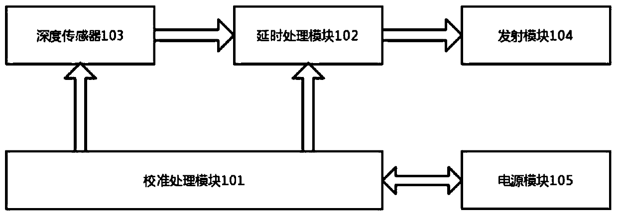
[0043] An embodiment of the present invention provides a depth sensor calibration system, such as figure 1 As shown, it includes a calibration processing module 101 , a delay processing module 102 , a depth sensor 103 and a transmitting module 104 .

[0044] Optionally, a power module 105 is also included.

[0045] The depth sensor calibration...


PUM


Abstract

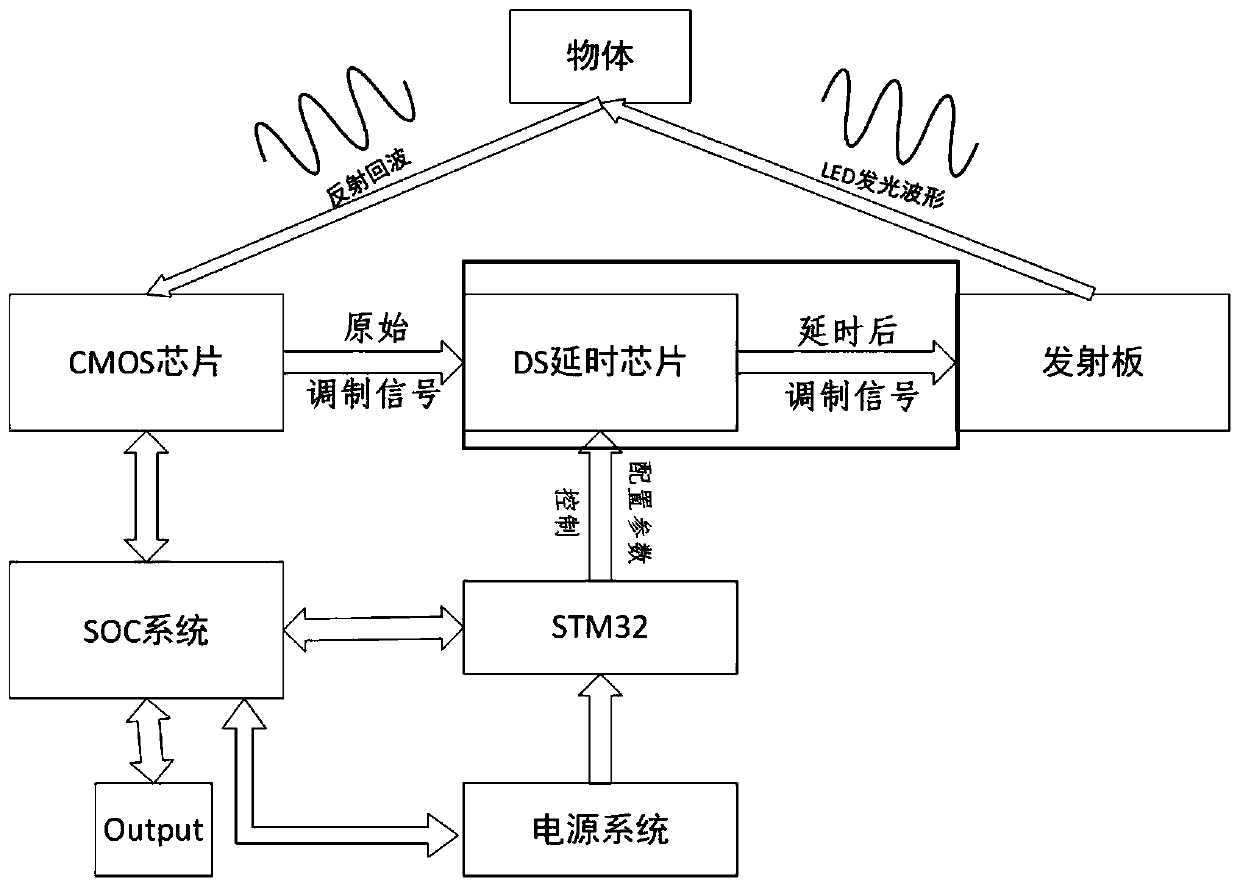
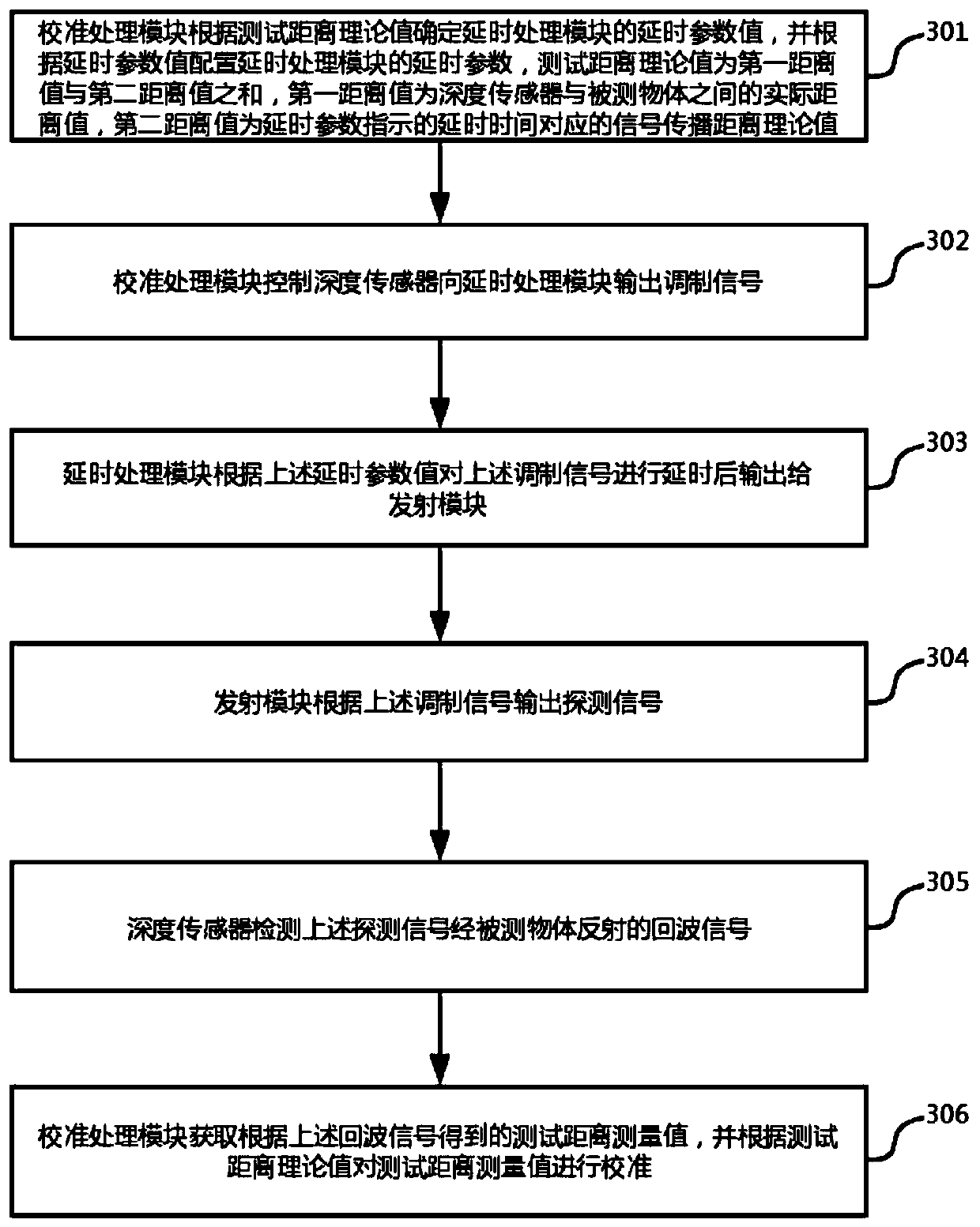
The embodiment of the invention provides a depth sensor calibration system and method. The system comprises a calibration processing module, a delay processing module, a depth sensor and a transmitting module. The calibration processing module determines a delay parameter value of the delay processing module according to a theoretical test distance and configures a delay parameter of the delay processing module according to the delay parameter value. The depth sensor is controlled to output a modulation signal to the delay processing module; a measurement distance obtained according to an echosignal is obtained and the measurement distance is calibrated based on the theoretical test distance. The delay processing module delays a modulation signal according to the delay parameter value configured by the calibration processing module and then outputs the modulation signal to the transmitting module. The transmitting module outputs a detection signal according to the modulation signal; and the depth sensor detects the echo signal reflected by the detected object by the detection signal. Therefore, the limitations of test environment, signal strength, test precision and the like can be reduced.

Description

technical field [0001] The embodiments of this specification relate to the technical field of depth sensors, and in particular to a depth sensor calibration system and method. Background technique [0002] The depth sensor based on TOF (time-of-flight) principle, its ranging principle is: the depth sensor sends out a detection signal, the detection signal encounters the measured object, is reflected by the measured object, the depth sensor receives the reflected echo signal, and calculates the return signal. The running time t of the wave signal is used to obtain the distance (Distance) between the measured object and the depth sensor according to the following formula 1, thus giving the depth information. [0003] Distance = c*t / 2 Formula 1 [0004] where c is the speed of light. [0005] The time difference between the detection signal transmission and the echo signal reception (that is, the above running time t) is calculated by using the four-step phase method, and the...

Claims


Application Information

Patent Timeline
Patent Type & Authority Applications(China)
IPC IPC(8): G01S7/497G01S17/08
CPCG01S7/497G01S17/08
Inventor 李旭兴刘行健梁炳寅疏达李远
Owner BENEWAKE BEIJING TECH CO LTD
Learn More