
Multi-linkage mechanism and linkage moving door

A linkage mechanism and linkage door technology, applied in the direction of windows/doors, building components, door/window accessories, etc., can solve problems such as unstable movement, noise, derailment, etc. sexual effect

Active Publication Date: 2019-12-17
瑞迹工业技术(上海)有限公司
View PDF7 Cites 0 Cited by
  • Summary
  • Abstract
  • Description
  • Claims
  • Application Information

AI Technical Summary

Problems solved by technology

[0005] Aiming at the problems of unstable movement, noise, inclination and even derailment in the prior art, the purpose of the present invention is to provide a multi-linkage mechanism and a linked moving door, which have the advantages of stable operation, no jamming, superior hand feeling, and convenient Advantages of installation, commissioning and disassembly

Method used


Image

  • Multi-linkage mechanism and linkage moving door
  • Multi-linkage mechanism and linkage moving door
  • Multi-linkage mechanism and linkage moving door

Examples


Embodiment 1

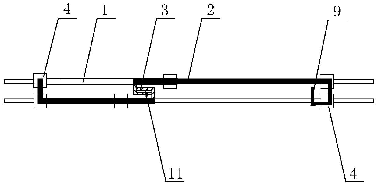
[0052] linkage moving door, such as figure 1 As shown, it includes two sliding rails 1 fixed parallel to each other. The two sliding rails 1 are connected to the linkage door 2 through roller sliding. The sliding rail 1 is parallel to the surface of the linkage door 2, and the two linkage doors 2 are installed adjacent to each other. There is a linkage hook 3 for realizing linkage. The linkage hook 3 is the prior art. After the linkage hook 3 overlaps, there is a transmission gap 11 between the two linkage hooks 3, so that the transmission between the linkage doors 2 is smoother. The side of the interlocking door 2 close to the outer side of the interlocking door 2 is integrally folded to form a folded edge 9. Since the opening of the hand slot 9 does not occupy the external space, the structure is more compact; the inner interlocking door 2 is wider than the outer interlocking door 2. Easy access to hem9. When in use, pull the inner linkage door 2 to slide through the folde...

Embodiment 2

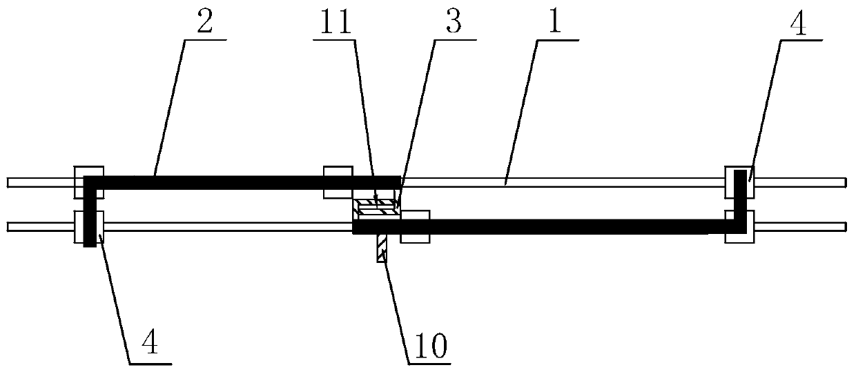
[0055] linkage moving door, such as figure 2 As shown, the difference from Embodiment 1 is that the two interlocking doors 2 are mirrored on the two slide rails 1, and the side of the outer interlocking door 2 far away from the inner interlocking door 2 is fixed to facilitate pulling the outer interlocking door 2. The outer handle 10 is convenient for the linkage door 2 to completely overlap to achieve the maximum door opening.

Embodiment 3

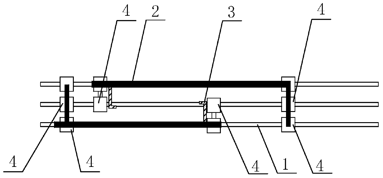
[0057] linkage moving door, such as image 3 As shown, the difference from Embodiment 1 is that the three slide rails 1 arranged parallel to each other are slidingly connected with the linkage door 2 on the slide rails 1 on both sides, and two Sliding piece 4, the sliding piece 4 is a roller, and the two rollers are slidingly connected to two adjacent slide rails 1 respectively, and a sliding piece 4 is fixed at the end of the linkage door 2 close to each other, and the sliding piece 4 slides It is connected to the sliding rail 1 in the middle, and by increasing the number of sliding rails 1 and sliding parts 4, the sliding stability of the linkage door 2 is further improved, the sliding noise is low, and the door opening feeling is more comfortable.


PUM


Abstract

The invention discloses a multi-linkage mechanism, and relates to the field of linkage structures. A first sliding rail and a second sliding rail are included and arranged in parallel and are in sliding connection with a first sliding object and a second sliding object. The sides, close to each other, of the first sliding object and the second sliding object are provided with a linkage hook for achieving linkage. The exterior of the straight line where the first sliding rail is located is provided with a first sliding piece in the length direction of the first sliding rail in a sliding manner,and the first sliding piece and the first sliding object are fixed. The exterior of the straight line where the second sliding rail is located is provided with a second sliding piece in the length direction of the second sliding rail in a sliding manner, and the second sliding piece and the second sliding object are fixed. For the problems about jamming or large resistance in the prior art, the sliding pieces are additionally arranged on the lower side of a linkage door and form a multi-wheel multi-guide-rail structure with a sliding part of the linkage door, accordingly, the linkage door running stability is improved, jamming is not likely to happen during usage, sliding noise is low, and more comfortable door opening touch feeling can be obtained.

Description

technical field [0001] The invention relates to the field of linkage structures, more specifically, it relates to a multi-linkage mechanism and a linkage moving door. Background technique [0002] Among the sliding doors, the linkage door is a commonly used door structure, which uses a multi-layer door structure instead of the entire door, and maximizes the view of the sliding door. [0003] For existing sliding door structures such as Figure 11 As shown, there are three sliding rails 1, on which there are linkage doors 2 slidingly connected by two rollers 4, and linkage hooks 3 are fixed on the side where the linkage doors are close to each other. By pulling the outermost linkage door, Then through the mutual driving of the linkage hooks, multiple linkage doors can completely close the door; Figure 7 As shown, the outermost linkage door is pulled to slide to realize the storage of multiple linkage doors, and the linkage doors are staggered to form a dislocation gap. [...

Claims


Application Information

Patent Timeline
Patent Type & Authority Applications(China)
IPC IPC(8): E06B3/46E06B3/48E05D13/00E06B7/28
CPCE05D13/00E06B3/4636E06B3/48E06B7/28
Inventor 叶政张风权
Owner 瑞迹工业技术(上海)有限公司
Learn More