
Steel bar stretching unit used for gear ring type steel prestress

A technology of prestressing and reinforcing steel bars, applied in the field of steel bar stretching units, can solve the problems of excessively long steel bar stretching, reducing the firmness and stability of buildings, and single function, and achieve the effect of improving practicability.

Pending Publication Date: 2019-12-17
江苏君睿智能制造有限公司
View PDF0 Cites 1 Cited by
  • Summary
  • Abstract
  • Description
  • Claims
  • Application Information

AI Technical Summary

Problems solved by technology

[0005] Aiming at the deficiencies of the prior art, the present invention provides a steel bar stretching unit used for ring gear steel prestressing, which has the advantages of convenient adjustment of the diameter of the steel bar and the same strength of the produced steel bar, and solves the problems of ordinary stretching machines on the market. The function is single, and the stretching length cannot be adjusted. If the steel bar is stretched too long, the quality cannot be guaranteed, which reduces the firmness and stability of the building. At the same time, the longer steel bar is stretched, but because the longer steel bar is stretched due to its own gravity Influenced by the influence, it is difficult to achieve uniform stress, resulting in the problem of steel bars of different strengths

Method used


Image

  • Steel bar stretching unit used for gear ring type steel prestress
  • Steel bar stretching unit used for gear ring type steel prestress
  • Steel bar stretching unit used for gear ring type steel prestress

Examples


Embodiment Construction

[0022] The following will clearly and completely describe the technical solutions in the embodiments of the present invention with reference to the accompanying drawings in the embodiments of the present invention. Obviously, the described embodiments are only some, not all, embodiments of the present invention. Based on the embodiments of the present invention, all other embodiments obtained by persons of ordinary skill in the art without making creative efforts belong to the protection scope of the present invention.

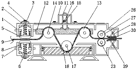
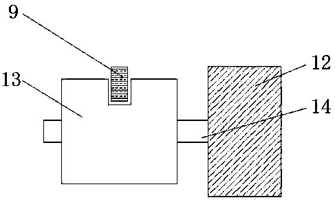
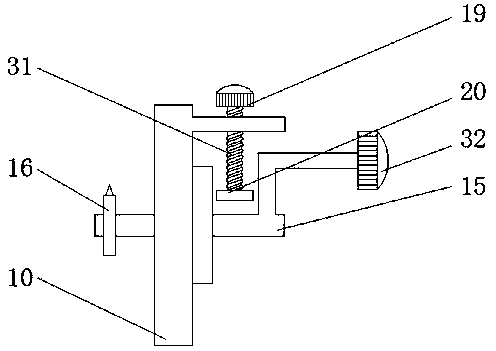
[0023] see Figure 1-4, a steel bar stretching unit used for ring gear steel prestressing, including a body 1, a trapezoidal block 2 is fixedly installed on the left side of the top of the body 1, a long rod 3 is movably socketed on the top of the trapezoidal block 2, and one end of the long rod 3 It runs through the trapezoidal block 2 and extends to the outside of the trapezoidal block 2 and is fixedly sleeved with a round button 4. The other end of the long...


PUM


Abstract

The invention relates to the technical field of steel bar machining devices and discloses a steel bar stretching unit used for gear ring type steel prestress. The steel bar stretching unit comprises aunit body, a trapezoidal block is fixedly mounted on the left side of the top of the unit body, a long rod is movably connected to the top of the trapezoidal block in a sleeved mode, one end of the long rod penetrates through the trapezoidal block, extends to the exterior of the trapezoidal block and is fixedly connected with a round button in a sleeved mode, the other end of the long rod sequentially penetrates through the trapezoidal block and the unit body, extends into the unit body and is movably connected with positioning blocks in a sleeved mode, and the outer surface of the long rod is movably connected with rigid springs in a sleeved mode, wherein the rigid springs are located between the positioning blocks and the inner wall of the unit body. One end of a to-be-stretched steel bar is wound around a roller and a cylinder and penetrates though the space between two idler wheels and two limiting blocks, at the moment, a motor is stated to enable the steel bar to pass though thepositioning blocks, the influence of the self gravity of the steel bar is avoided because of cooperation between the positioning blocks and the long rod as well as cooperation between the positioningblocks and the rigid springs, uniform force bearing is realized, thus the strength of the stretched steel bar is same, and the practicability of the stretching unit is improved.

Description

technical field [0001] The invention relates to the technical field of steel bar processing devices, in particular to a steel bar stretching unit used for ring gear steel prestressing. Background technique [0002] The steel bar stretching unit is one of the steel bar processing machines. Its appearance greatly saves the use of steel bars and saves economic expenditures. It increases the utilization rate of steel bars and further enhances the strength of steel bars. It improves the quality of the project and makes the building Things become stronger, and the steel bar stretching unit has occupied an important position in steel bar processing. [0003] However, the ordinary stretching units on the market have single functions, and the stretching length cannot be adjusted, so that the quality of the steel bar cannot be guaranteed if it is stretched too long, which reduces the firmness and stability of the building. Due to the influence of its own gravity when the long steel b...

Claims


Application Information

Patent Timeline
IPC IPC(8): B21C1/02B21C1/12
CPCB21C1/02B21C1/12
Inventor 李沈翼
Owner 江苏君睿智能制造有限公司
Learn More