
Electrical equipment

A technology for electrical equipment and cables, applied in the field of electrical equipment, can solve the problems of the cable sheath being pulled out of the casing and the cable sheath failing to protect the cable, so as to reduce the possibility of sliding and loosening, and is reliable. fixed effect

Pending Publication Date: 2019-12-13
HUAWEI TECH CO LTD
View PDF0 Cites 3 Cited by
  • Summary
  • Abstract
  • Description
  • Claims
  • Application Information

AI Technical Summary

Problems solved by technology

Taking the wiring board as an example, some current wiring boards form half holes at the parting places of the upper and lower shells of the shell, and the cable sheath is installed at the parting places of the upper and lower shells, using half holes in the upper and lower shells When the material of the cable sheath is aged, or the parting part is slightly expanded or loosened, the cable sheath is easily pulled out of the housing, causing the cable sheath to damage the cable. protection failure

Method used


Image

  • Electrical equipment
  • Electrical equipment
  • Electrical equipment

Examples


Embodiment Construction

[0044] The technical solutions in the embodiments of the present application will be clearly described below with reference to the drawings in the embodiments of the present application. Apparently, the described embodiments are some of the embodiments of the present application, not all of them. Based on the embodiments of the present application, other embodiments obtained by persons of ordinary skill in the art without making creative efforts all belong to the protection scope of the present application.

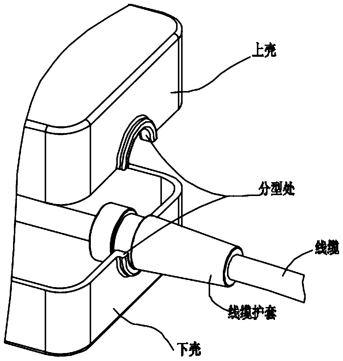
[0045] figure 1 It is a schematic diagram of the cable sheath fixing structure of some electrical equipment at present.

[0046] Such as figure 1 As shown, in some current electrical equipment, half holes are formed at the parting places of the upper and lower shells of the shell, and the cable sheath is installed at the parting places of the upper and lower shells. The cable sheath is fixed in position. When the material of the cable sheath is aged, or the parting par...


PUM


Abstract

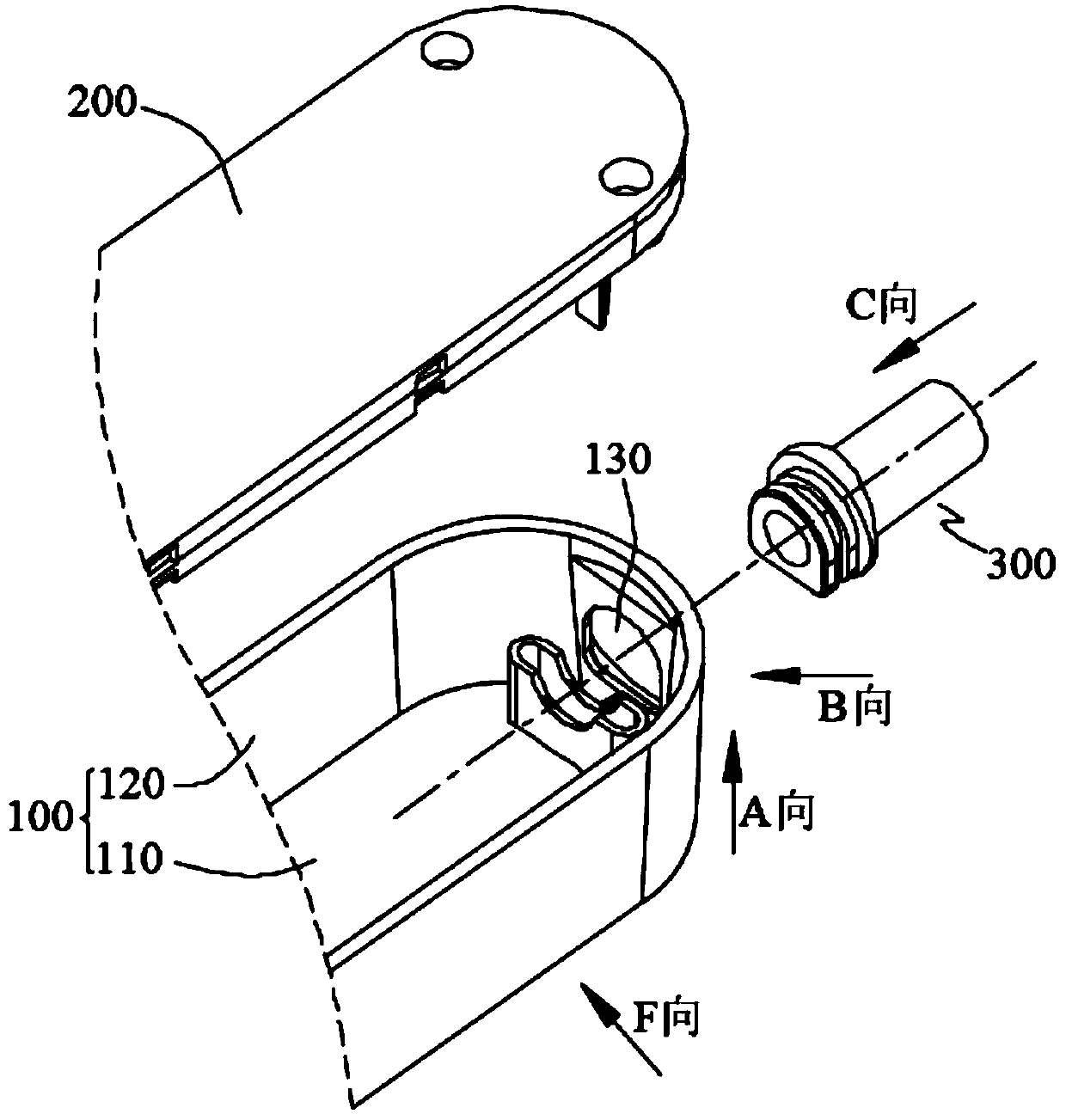
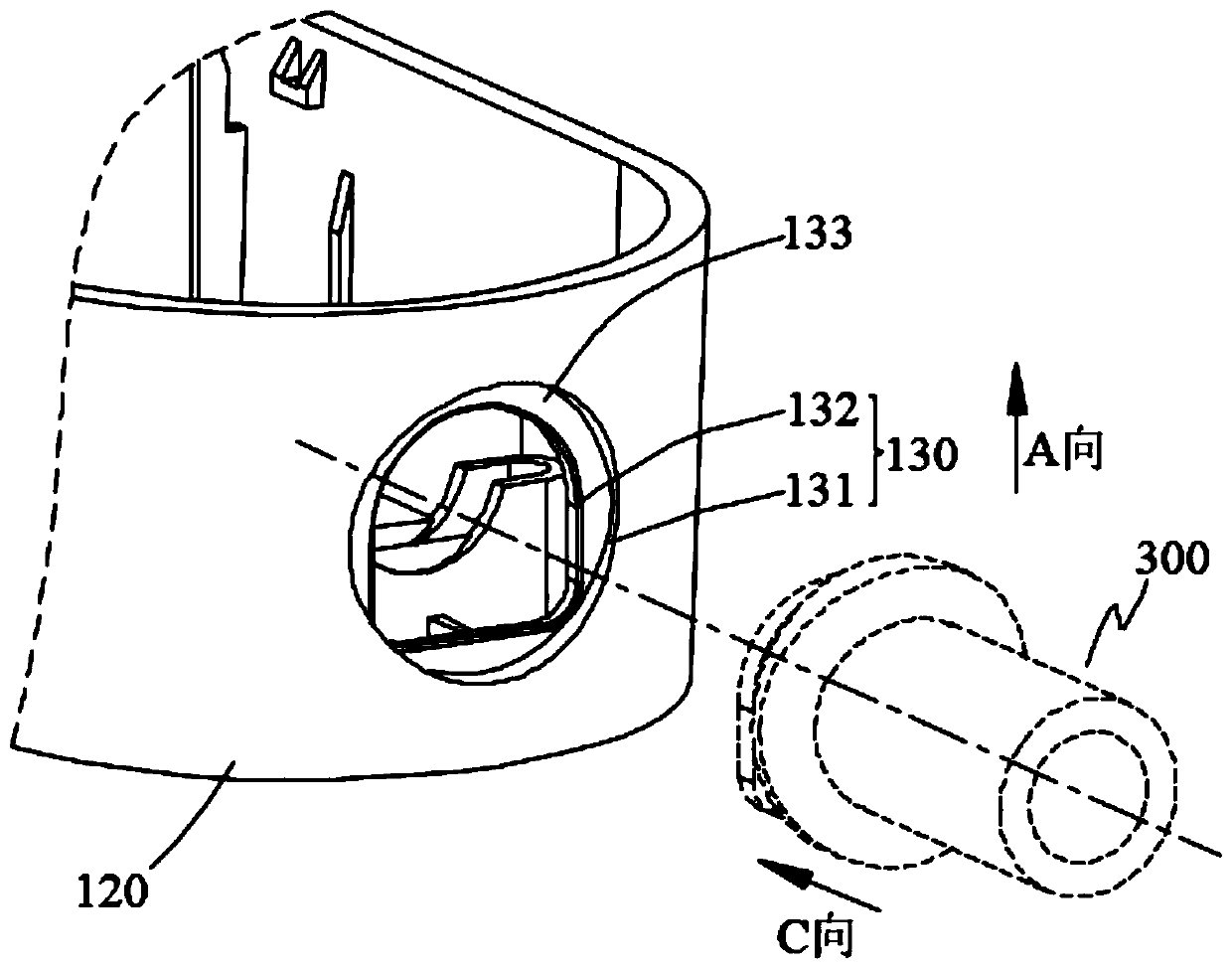
The embodiment of the invention provides electrical equipment. The electrical equipment comprises a first shell, a second shell and a cable sheath, wherein the first shell comprises a wire inlet holecomposed of a limiting hole and a rotation stopping hole, and the cable sheath correspondingly comprises a limiting sleeve shoulder and a rotation stopping sleeve shoulder; the second shell comprisesa positioning rib, and the rotation stopping sleeve shoulder further correspondingly comprises a limiting groove. The cable sheath is arranged in the wire inlet hole in a penetrating manner, so that the rotation stopping hole and the rotation stopping sleeve shoulder are in hole-shaft fit, and the cable sheath is prevented from rotating relative to the first shell; and the limiting sleeve shoulderand the limiting hole are in hole-shaft fit, so that the cable sheath is prevented from moving in the direction of penetrating into the cable inlet hole. Therefore, according to the technical schemeprovided by the embodiment of the invention, the cable sheath can be reliably fixed, the possibility that the cable sheath slides and gets loose relative to the electrical equipment is reduced, and the cable of the electrical equipment is effectively protected.

Description

technical field [0001] The present application relates to the technical field of power electronics, and in particular to an electrical device. Background technique [0002] Some electrical equipment, such as: wiring boards, power adapters, electric fans, air conditioners, etc., all have power cables, so as to be connected to the power socket by the power cables to obtain long-distance power supply. [0003] During the use of electrical equipment, the insulating sheath of the cable is subjected to long-term effects of external forces such as equipment movement, machine vibration, and dragging, twisting, and bending. Leakage, short circuit and other safety issues. Therefore, in order to protect the cable, a cable sheath is usually provided at the connection between the housing of the electrical equipment and the cable, so that the cable passes through the cable sheath to avoid direct contact between the housing and the cable, to achieve The purpose of protecting the cable. ...

Claims


Application Information

Patent Timeline
IPC IPC(8): H01R13/502H01R13/512H01R13/56H01R13/58
CPCH01R13/56H01R13/562H01R13/565H01R13/5812H01R13/5816H01R13/5825H01R13/502H01R13/512
Inventor 程良军
Owner HUAWEI TECH CO LTD
Learn More