
Anti-interference coil module and device

A coil module and coil device technology, which is used in measurement devices, radio wave measurement systems, and sound wave re-radiation, etc., can solve problems such as non-compliance with transient electromagnetic laws, slow curve attenuation, and large distortion, and eliminate aliasing. phenomenon, the effect of increasing the emission current and reducing the influence of mutual inductance

Inactive Publication Date: 2019-12-13
武汉地大华睿地学技术有限公司
View PDF0 Cites 0 Cited by
  • Summary
  • Abstract
  • Description
  • Claims
  • Application Information

AI Technical Summary

Problems solved by technology

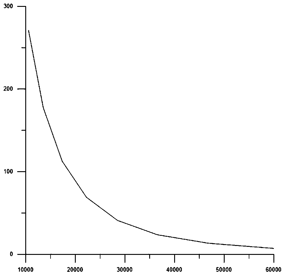
Due to the strong mutual inductance of ordinary figure-eight coils, the attenuation of the curve in Figure 4 slows down, especially the attenuation of the late stage, the distortion is very large, and it does not conform to the law of transient electromagnetics, so the actual use effect does not match the actual geological conditions

Method used


Image

  • Anti-interference coil module and device
  • Anti-interference coil module and device
  • Anti-interference coil module and device

Examples


Embodiment 1

[0033] Such as Figure 5 As shown, an anti-jamming coil module includes a transmitting coil 1 and a receiving coil 2 disposed in the transmitting coil 1 , and also includes a compensation coil 3 disposed in the receiving coil 2 .

[0034] The compensation structure of Embodiment 1 is called central compensation, and its compensation mechanism is: the magnetic field generated by the transmitting coil 1 inside the receiving coil 2 and the primary magnetic field generated by the compensation coil cancel each other out, ie: φtransmission=φcompensation.

Embodiment 2

[0036] Such as Figure 6 As shown, an anti-interference coil module includes a transmitting coil 1, and a receiving coil 2 arranged in the transmitting coil 1, and also includes a compensation coil 3, and the compensation coil 3 is arranged between the transmitting coil 1 and the Between the receiving coil 2.

[0037] The compensation structure of the second embodiment is called internal compensation, and its compensation mechanism is: the magnetic field generated by the transmitting coil 1 inside the receiving coil 2 and the primary magnetic field generated by the compensation coil cancel each other out, that is: φtransmission=φcompensation.

[0038] In Embodiment 1 or Embodiment 2 or other embodiments: the transmitting coil 1 , the receiving coil 2 and the compensating coil 3 are combined into a rigid structure. Such as Figure 7 and Figure 8 As shown, the specific present invention also includes a plastic frame 5, and the transmitting coil 1, the receiving coil 2 and th...


PUM


Abstract

The invention relates to a transient electromagnetic coil and particularly relates to an anti-interference coil module and device. The module comprises a transmitting coil, a receiving coil disposed in the transmitting coil, and a compensation coil which is disposed in the receiving coil or between the transmitting coil and the receiving coil. The device comprises a middle junction box and a plurality of anti-interference coil modules, and the plurality of anti-interference coil modules are connected through the middle junction box to form one or more double-splayed coils. The module can eliminate an aliasing phenomenon of a primary field and a secondary field of a conventional receiving coil and reduces the influence of mutual inductance. The device provided by the invention adopts a modular structure and has the advantages of high flexibility and strong in anti-interference capability, and the low-voltage large-current emission can be achieved.

Description

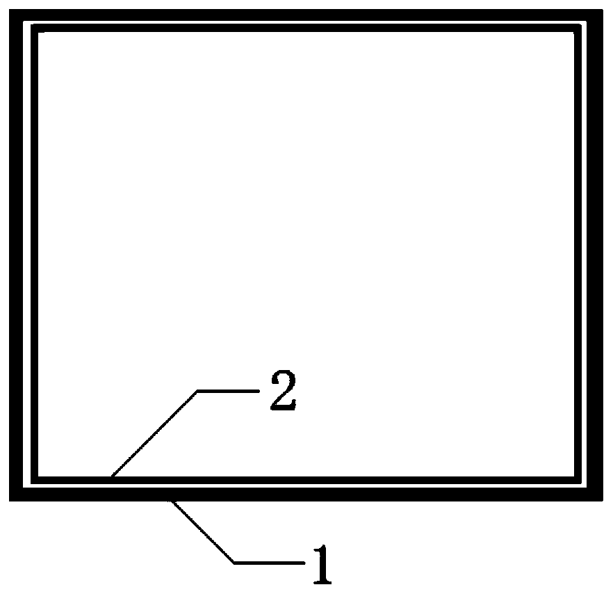
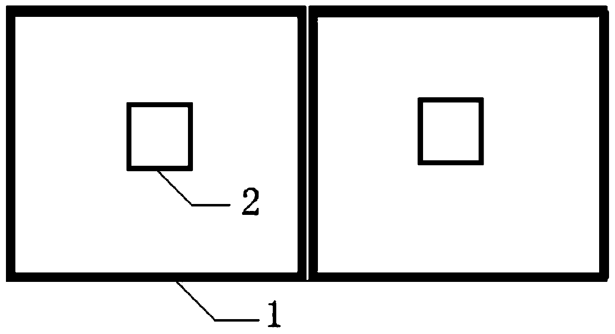
technical field [0001] The invention relates to transient electromagnetic coils, in particular to an anti-interference coil module and device. Background technique [0002] Transient Electromagnetic Methods (TEM for short) belongs to a geophysical prospecting method. This method uses an ungrounded return line or a grounded line source to transmit a pulsed magnetic field underground. During the interval of a pulsed magnetic field, the coil Or the method of observing the secondary eddy current field with the ground electrode. It is mainly used in engineering geological exploration, metal mineral exploration, coal mine exploration and other fields. [0003] Current transient electromagnetic antenna coils such as figure 1 and image 3 structure of coils, figure 1 The normalized potential difference curve of the common loop coil shown is as follows figure 2 as shown, figure 2 The decay curve in includes primary field and inductive effects, image 3 The normalized potenti...

Claims


Application Information

Patent Timeline
Patent Type & Authority Applications(China)
IPC IPC(8): G01V3/10
CPCG01V3/10
Inventor 梁庆九
Owner 武汉地大华睿地学技术有限公司
Learn More