
Rotating speed prediction method and system and vehicle

A prediction method and prediction system technology, applied in the direction of linear/angular velocity measurement, velocity/acceleration/shock measurement, measuring device, etc., can solve problems such as poor timeliness, easy overshoot, poor PID control effect, etc., to improve ride comfort , Improve the effect of the control effect

Inactive Publication Date: 2019-12-13
深圳臻宇新能源动力科技有限公司
View PDF6 Cites 5 Cited by
  • Summary
  • Abstract
  • Description
  • Claims
  • Application Information

AI Technical Summary

Problems solved by technology

However, in actual control, the speed signal is delayed (especially the engine speed is transmitted from the ECU (Electronic Control Unit, electronic control unit) to the TCU (Transmission Control Unit, automatic transmission) through the CAN (Controller Area Network, controller area network) network. Control unit) delay is more obvious, when the actual speed is far away from the target speed, if the PID is too large, it is easy to overshoot, if the PID is too small, it is easy to cause risks such as excessive slippage
[0003] At present, the relevant PID control strategy usually uses the actual speed for calculation. The timeliness of this method is poor and the response speed is slow, resulting in poor PID control effect.

Method used


Image

  • Rotating speed prediction method and system and vehicle
  • Rotating speed prediction method and system and vehicle

Examples


Embodiment Construction

[0036] Embodiments of the present invention are described in detail below, examples of which are shown in the drawings, wherein the same or similar reference numerals designate the same or similar elements or elements having the same or similar functions throughout. The embodiments described below by referring to the figures are exemplary only for explaining the present invention and should not be construed as limiting the present invention.

[0037]In describing the present invention, it should be understood that the terms "center", "longitudinal", "transverse", "upper", "lower", "front", "rear", "left", "right", " The orientations or positional relationships indicated by "vertical", "horizontal", "top", "bottom", "inner" and "outer" are based on the orientations or positional relationships shown in the drawings, and are only for the convenience of describing the present invention and Simplified descriptions, rather than indicating or implying that the device or element refer...


PUM


Abstract

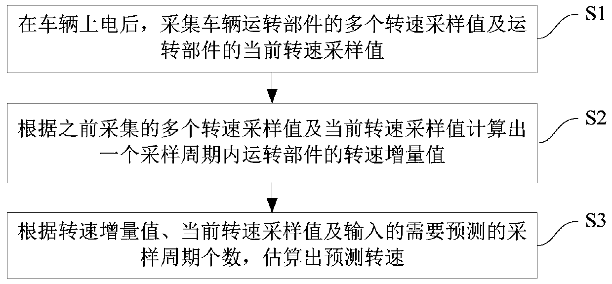
The invention provides a rotating speed prediction method and system and a vehicle, and the method can be used in the field of rotating speed control of vehicles, ships and the like. The method comprises the following steps: collecting a plurality of rotating speed sampling values of an operating part of a vehicle and a present rotating speed sampling value of the operating part after the vehicle(or other equipment, hereinafter taking the automobile as an example) is powered on; calculating a rotating speed increment value of the operating part in one sampling period according to a pluralityof previously acquired rotating speed sampling values and the present rotating speed sampling value; and estimating the predicted rotating speed according to the rotating speed increment value, the present rotating speed sampling value and the number of input sampling periods needing to be predicted. According to the method, the change trend of the present rotating speed can be effectively identified, so that the rotating speed in the future can be quickly and accurately predicted, the PID control effect can be improved, and the smoothness of the vehicle is improved.

Description

technical field [0001] The invention relates to the field of speed control of vehicles, ships, etc., in particular to a speed prediction method, system and vehicle, which can be applied to the speed prediction of engine speed, input shaft speed and other speeds of automobiles and other equipment. Background technique [0002] In the development process of automobile transmission, the clutch torque control often controls the speed difference (the difference between the target speed and the actual speed) through PID (Proportion-Integral-Differential, proportional-integral-differential), that is, the torque is equal to the gain item of PID and the speed difference The product of , so the size of the speed difference directly affects the size of the torque. But when the target speed is determined, the actual speed directly determines the torque trend. However, in actual control, the speed signal is delayed (especially the engine speed is transmitted from the ECU (Electronic Con...

Claims


Application Information

Patent Timeline
Patent Type & Authority Applications(China)
IPC IPC(8): G01P3/00
CPCF16H2061/0078G01P3/00
Inventor 莫润波叶腾平
Owner 深圳臻宇新能源动力科技有限公司
Learn More