
Stacking device and loading machine

A stacking and racking technology, applied in the directions of transportation and packaging, loading/unloading, stacking of objects, etc., can solve the problems of large moving space, limit the stacking space range of the stacking device of the frame design of the loader, and increase the moving space. , to avoid the effect of overall instability and compact overall structure

Pending Publication Date: 2019-12-13
CHINA HEFEI TAIHE OPTOELECTRONICS TECH
View PDF0 Cites 0 Cited by
  • Summary
  • Abstract
  • Description
  • Claims
  • Application Information

AI Technical Summary

Problems solved by technology

In this way, when the stacking device moves up and down and in the front and rear directions, a large moving space must be reserved for these auxiliary parts, which limits the frame design of the loading machine and the stacking space range of the stacking device.

Method used


Image

  • Stacking device and loading machine
  • Stacking device and loading machine
  • Stacking device and loading machine

Examples


no. 1 example

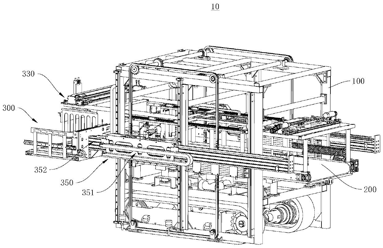
[0035] See figure 1 In this embodiment, a vehicle loading machine 10 is provided, which is used to store goods on the loading plane inside the vehicle compartment (not shown). Among them, the overall structure of the loading machine 10 is compact, which can improve the overall stability and expand the stacking range.

[0036] It should be noted that the loading machine 10 is used to be placed on the cargo plane inside the carriage, and can move on the cargo plane, so as to transport the goods to the designated position and store the goods in the designated position, thereby making The goods can be neatly stacked on the cargo plane. In addition, the loading machine 10 is connected to a conveying device (not shown) for conveying goods. The conveying device transports the goods from the warehouse or other places to the loading machine 10. The loading machine 10 can accept the goods conveyed by the conveying device and The goods are moved and stacked to the designated location.

[00...

no. 2 example

[0079] This embodiment provides a loading system (not shown), which uses the loading machine 10 provided in the first embodiment, and the overall structure of the loading system is compact, which can improve overall stability and expand Stacking range.


PUM


Abstract

The invention provides a stacking device and a loading machine, and relates to the technical field of loading. The stacking device is used for being mounted on a rack, is connected with a conveying line on the rack, and comprises a stacking platform, a pushing assembly and a comb tooth structure, wherein the stacking platform is used for receiving goods conveyed by the conveying line, the comb tooth structure is movably mounted at the bottom of the stacking platform, the comb tooth structure can selectively form a guiding structure or eliminate the guiding structure on the stacking platform, the pushing assembly is movably connected to the stacking platform, and the pushing assembly can slide along the guiding structure to push out the goods. The invention further provides the loading machine which adopts the stacking device. The stacking device and the loading machine are compact in overall structures, the overall stability can be improved, and the stacking range can be enlarged.

Description

Technical field [0001] The present invention relates to the technical field of loading, in particular to a stacking device and a loading machine. Background technique [0002] In the field of production and logistics, with the gradual increase in labor costs and the increase in scale and automation of production methods, the demand for automatic loading equipment is increasing. In the prior art, the front end of the automatic loading machine generally has a stacking device, and a cargo pushing mechanism is arranged on the stacking device, and the cargo pushing mechanism pushes the cargo on the stacking device into the carriage for stacking. The driving mechanism of the pushing mechanism is generally realized by a servo motor or an air cylinder. Because the pushing stroke of the pushing mechanism is relatively large, a guide rail, a guide rod, a screw rod, etc. are generally used to ensure the stability of the pushing mechanism during the pushing process. Generally, the driving m...

Claims


Application Information

Patent Timeline
IPC IPC(8): B65G67/04B65G61/00
CPCB65G67/04B65G61/00
Inventor 许大红石江涛武怀斌翟新姚占勇张杰
Owner CHINA HEFEI TAIHE OPTOELECTRONICS TECH
Learn More