
Efficient and accurate positioning system and positioning method for parts uniformly distributed in circumferential direction

A uniformly distributed and precise positioning technology, applied in the direction of measuring devices, instruments, manipulators, etc., can solve problems such as difficulty in determining the radius and center of circle, occupying a large amount of work time, and time-consuming, so as to achieve high actual efficiency, shorten working time, and reasonable methods Effect

Inactive Publication Date: 2019-12-13
扬州哈工科创机器人研究院有限公司
View PDF6 Cites 2 Cited by
  • Summary
  • Abstract
  • Description
  • Claims
  • Application Information

AI Technical Summary

Problems solved by technology

The method of manual teaching requires a lot of work time. If machine vision is used for positioning, limited by the field of view of the industrial smart camera, only a single local screw can be photographed and positioned within a fixed range. Once the number of screws is large, each screw should be photographed and positioned. undoubtedly time consuming
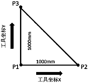
On the other hand, for the vast majority of existing robots, the arc trajectory programming method is given three reference points: the arc start point, the arc middle point and the arc end point, which are fitted into a section of arc. The way is difficult to determine the radius and center of the circle

Method used


Image

  • Efficient and accurate positioning system and positioning method for parts uniformly distributed in circumferential direction
  • Efficient and accurate positioning system and positioning method for parts uniformly distributed in circumferential direction
  • Efficient and accurate positioning system and positioning method for parts uniformly distributed in circumferential direction

Examples


Embodiment Construction

[0026] In order to make the purpose, technical solutions and advantages of the embodiments of the present invention clearer, the technical solutions in the embodiments of the present invention will be clearly and completely described below in conjunction with the drawings in the embodiments of the present invention. Obviously, the described embodiments It is a part of embodiments of the present invention, but not all embodiments. Based on the embodiments of the present invention, all other embodiments obtained by persons of ordinary skill in the art without making creative efforts belong to the protection scope of the present invention.

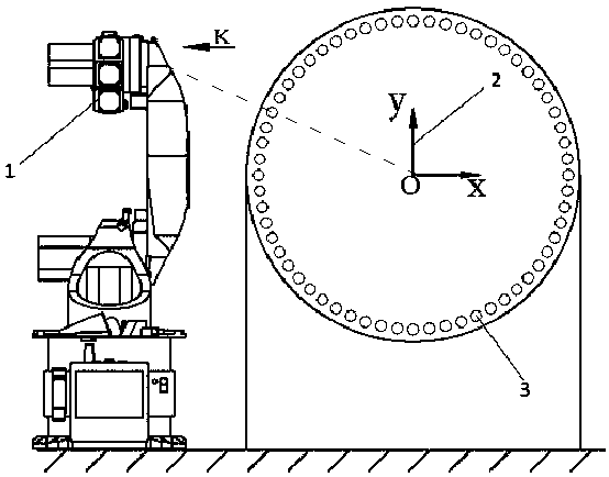
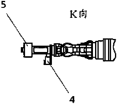
[0027] The present invention provides a positioning method based on visual laser-based circumferential distribution parts, the state of the circumferential distribution of the parts is as follows: Figure 1-2 As shown, it includes industrial robot 1, robot tool coordinate system TCP 2, screw circumferential distribution state 3, visual laser ...


PUM


Abstract

The prevent invention discloses an efficient and accurate positioning system and positioning method for parts uniformly distributed in circumferential direction. With the rise of industrial robots, alarge number of industries introduce robots to replace labor, thus improving work efficiency and product quality, and improving the intelligent level of manufacturing industry as a whole. For example,the tightening and assembling of circumferential screws of large-scale parts is time-consuming and laborious by manual assembly, and the quality is often not up to the requirements. The positioning system comprises an industrial robot, a robot tool coordinate system, circumferential parts, a vision system and a laser measuring system, wherein the industrial robot is provided with a tool, and thetool is a screw tightening device installed at the tail end of the robot according to screw specifications; the vision system comprises a light source and a camera, and the vision system is a system for data interaction with the industrial robot; and the laser measuring system is a system capable of measuring distance values in a required range and transmitting data to the robot. The positioning system and positioning method are used for efficient and accurate positioning of parts uniformly distributed in the circumferential direction.

Description

Technical field: [0001] The invention relates to the field of intelligent assembly of parts, in particular to an efficient and precise positioning system and positioning method for evenly distributed parts on the circumference. Background technique: [0002] With the rise of industrial robots, a large number of industries have introduced robots to replace labor, thereby improving work efficiency and product quality, and improving the intelligence level of the manufacturing industry as a whole. For example, the circumferential screw tightening assembly of large parts, manual assembly is time-consuming and laborious, and the quality often does not meet the requirements. [0003] Therefore, it is necessary to introduce industrial robots to replace human labor. There are currently two mainstream application methods for industrial robots: one is to carry out operations through pre-programmed trajectories, the so-called manual teaching method; the other is to use intelligent sens...

Claims


Application Information

Patent Timeline
IPC IPC(8): B25J9/02B25J9/10B25J9/16G01B11/02G01B11/26
CPCB25J9/023B25J9/10B25J9/1697B25J9/1664G01B11/02G01B11/26
Inventor 蒋思明赵小东衣超马浚峰寇江伟张广才
Owner 扬州哈工科创机器人研究院有限公司
Learn More