
Undercarriage testing plane mounting support assembly process and tool

A technology for installing supports and testing machines, which is applied in the direction of manufacturing tools, workpiece clamping devices, etc., and can solve problems such as low precision and dimensional precision, dependence on the quality of operators, and high labor intensity of workers

Active Publication Date: 2019-12-13
YANSHAN UNIV
View PDF9 Cites 1 Cited by
  • Summary
  • Abstract
  • Description
  • Claims
  • Application Information

AI Technical Summary

Problems solved by technology

[0006] According to the above proposals, the use of general measuring tools for detection and manual adjustment results in low relative position accuracy and dimensional accuracy of parts such as the main rotary support, retractable actuator support and landing gear lock support on the test machine frame, and the labor intensity of workers is low. large and the final quality depends on the quality of the operator, and provides an assembly process and tooling for the mounting support of the landing gear testing machine

Method used


Image

  • Undercarriage testing plane mounting support assembly process and tool
  • Undercarriage testing plane mounting support assembly process and tool
  • Undercarriage testing plane mounting support assembly process and tool

Examples


Embodiment 1

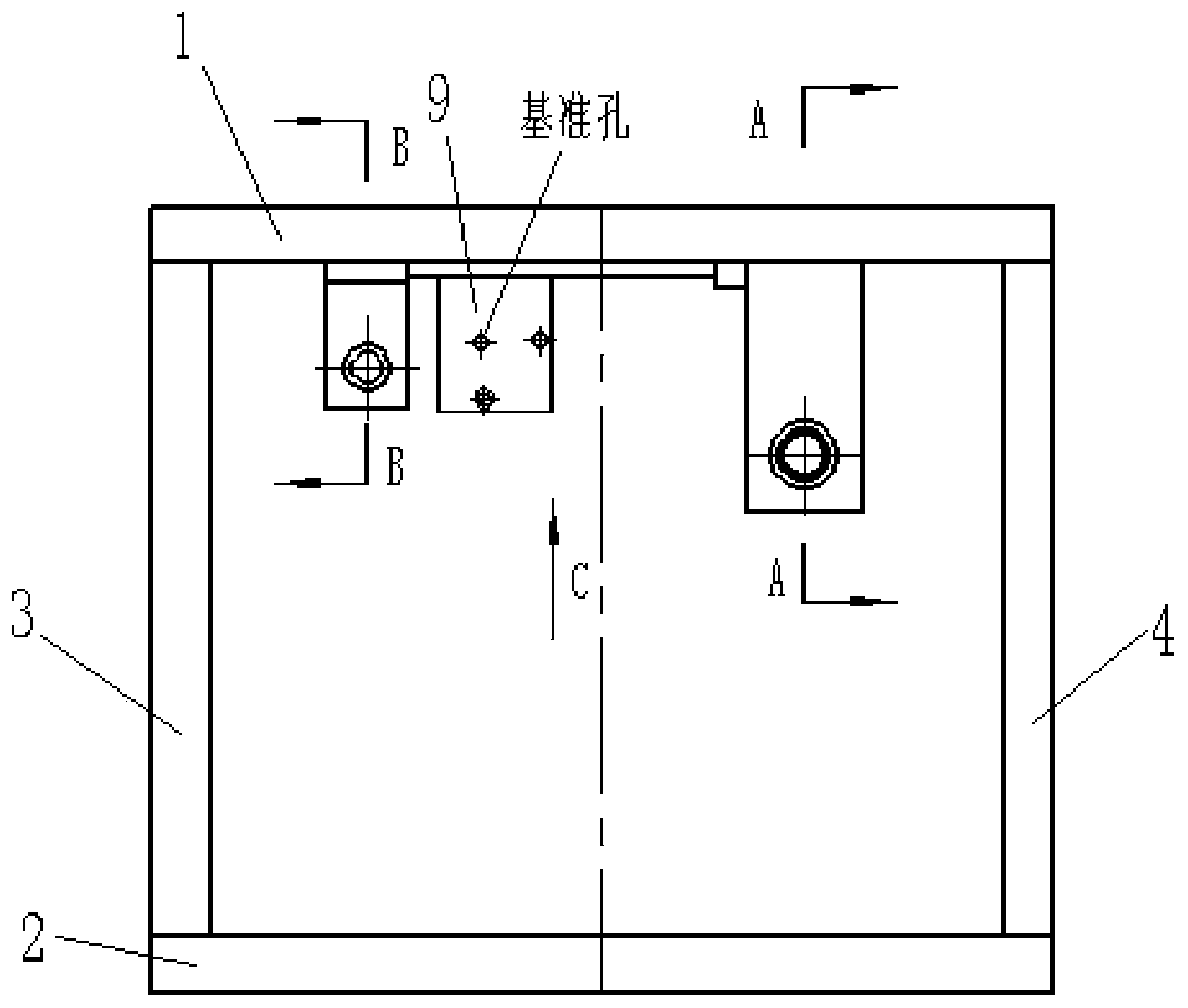
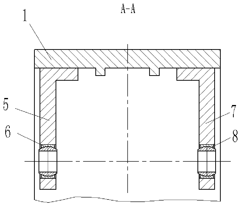
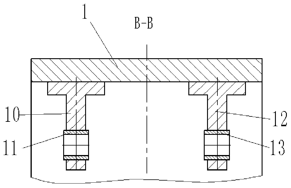
[0063] Such as Figure 1-11 As shown, the present invention provides a kind of landing gear testing machine mounting support tooling, comprises testing machine frame upper beam 1, testing machine frame base 2, test machine frame left column 3, test machine frame left and right columns 4, Main slewing support A5, joint bearing A6, main slewing support B7, joint bearing B8, landing gear lock support 9, retractable actuator support A10, copper sleeve A11, retractable actuator support B12, copper Sleeve B13, main slewing support installation mandrel 14, main slewing support installation tool 15, retractable actuating cylinder support installation mandrel 16, retractable actuating cylinder support installation tool A17, retractable actuating cylinder support Install tooling B18, reference block A19, reference bar A20, reference bar B21, reference block B22 and other components.

[0064] The lower surface of the test machine frame base 2 is fixed on the concrete foundation, the lef...

Embodiment 2

[0072] On the basis of embodiment 1, the present invention also provides a kind of landing gear testing machine mounting support assembly process that adopts the landing gear testing machine mounting support tooling to install the landing gear testing machine mounting support, comprising the following steps:

[0073] S1. Install the joint bearing A6 into a suitable position in the through-cylindrical through hole on the first rectangular vertical plate of the main slewing support A5 and fix it;

[0074] S2. Install the joint bearing B8 into a suitable position in the through-cylindrical through hole on the first rectangular vertical plate of the main slewing support B7 and fix it;

[0075] S3, put the copper sleeve A11 into the suitable position in the through-cylinder through hole on the second rectangular vertical plate of the retractable actuator support A10 and fix it;

[0076] S4, put the copper sleeve B13 into the appropriate position in the through-cylinder through hole o...


PUM


Abstract

The invention provides an undercarriage testing plane mounting support tool. The undercarriage testing plane mounting support tool comprises a testing plane-shaped frame upper beam, a test plane-shaped frame bottom seat, a testing plane-shaped frame left stand column, a testing plane-shaped frame right stand column, a main pivoting support A, a knuckle bearing A, a main pivoting support B, a knuckle bearing B, an undercarriage lock support, a retraction and release actuation cylinder support A, a copper sleeve A, a retraction and release actuation cylinder support B, a copper sleeve B, a mainpivoting support installing core shaft, a main pivoting support installing tool, a retraction and release actuation cylinder support installing core shaft, a retraction and release actuation cylindersupport installing tool A, a retraction and release actuation cylinder support installing tool B, a reference block A, a reference strip A, a reference strip B and a reference block B. The undercarriage testing plane mounting support tool can realize precise installation of an undercarriage testing plane, and substantially reduces labor intensity of workers.

Description

technical field [0001] The invention relates to an assembly process and tooling for a mounting support of a landing gear testing machine. Background technique [0002] Landing gear is one of the key components of a fighter, and its performance, reliability, and stability will directly affect the flight safety of the fighter. Therefore, various ground performance tests must be carried out on the fighter landing gear before installation. [0003] The ground performance test of the landing gear is generally to install the landing gear on the test frame according to the real working posture, and then conduct various performance tests. The test machine frame is provided with the main slewing support, retractable actuator support, support rod installation and fabrication, landing gear lock support, etc. as connection interfaces, and the landing gear is installed through these interfaces. [0004] In order to ensure the authenticity and reliability of the ground performance test ...

Claims


Application Information

Patent Timeline
IPC IPC(8): B25B11/00
CPCB25B11/00
Inventor 臧新良刘喜平姚静
Owner YANSHAN UNIV
Learn More