
Laser scanning imaging equipment

A technology of laser scanning imaging and equipment, which is applied in optics, image communication, image reproducer using projection devices, etc., can solve the problems of circuit and laser performance degradation, and achieve the effect of continuous display, lower cost and lower performance requirements.

Active Publication Date: 2019-12-10
CHENGDU IDEALSEE TECH
View PDF6 Cites 0 Cited by
  • Summary
  • Abstract
  • Description
  • Claims
  • Application Information

AI Technical Summary

Problems solved by technology

[0005] The embodiment of the present invention provides a laser scanning imaging device to solve the technical problem in the prior art that the performance of the circuit and the laser is degraded due to the continuous high-frequency pulse modulation of the laser scanning imaging technology

Method used


Image

  • Laser scanning imaging equipment
  • Laser scanning imaging equipment
  • Laser scanning imaging equipment

Examples


Embodiment Construction

[0029] The following will clearly and completely describe the technical solutions in the embodiments of the present invention with reference to the accompanying drawings in the embodiments of the present invention. Obviously, the described embodiments are only some, not all, embodiments of the present invention. Based on the embodiments of the present invention, all other embodiments obtained by persons of ordinary skill in the art without creative efforts fall within the protection scope of the present invention.

[0030] An embodiment of the present invention provides a laser scanning imaging device, which is used to solve the technical problem existing in the prior art that the performance of circuits and lasers is degraded due to high-frequency pulse modulation of the laser scanning imaging technology.

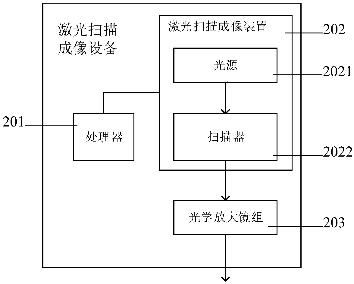
[0031] An embodiment of the present invention provides a laser scanning imaging device, please refer to figure 2 , figure 2 Schematic diagram of the structure of the la...


PUM


Abstract

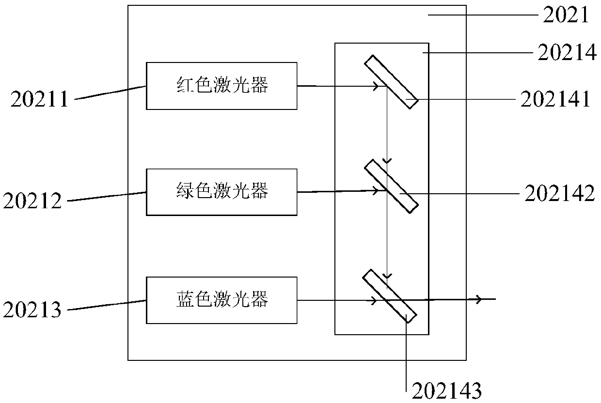
The invention discloses laser scanning imaging equipment. The equipment comprises a processor and laser scanning imaging equipment, the laser scanning imaging equipment comprises a light source and ascanner, light emitted by the light source is formed by combining light of different colors emitted by three lasers, and the three lasers are in one-to-one correspondence with three color channels ofeach pixel in an image to be scanned; in the process of scanning two adjacent pixels in a to-be-scanned image, when the numerical value of at least one color channel of the two adjacent pixels is thesame, the processor controls the lasers corresponding to the color channels with the same numerical value to emit light continuously. According to the invention, the modulation frequency of the circuit and the laser is reduced, the reliability of the whole laser scanning imaging equipment is improved, and the service life of the laser scanning imaging equipment is prolonged.

Description

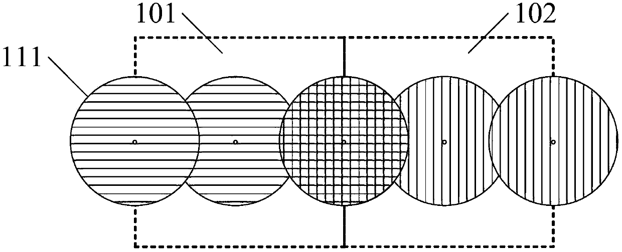
technical field [0001] The invention relates to the field of laser scanning projection, in particular to a laser scanning imaging device. Background technique [0002] Laser scanning imaging refers to the use of laser light as a light source, scanning on the image plane with a laser scanning imaging device according to a preset method, and at the same time changing the color of the emitted laser light, so that laser scanning imaging can be realized on the image plane. [0003] Currently, in the process of realizing laser scanning imaging, please refer to figure 1 , figure 1 It is a schematic diagram of laser scanning imaging in the prior art, such as figure 1 As shown, when the scanning point corresponding to the laser scanning imaging device enters the pixel area 101, it starts to control the laser in the light source to emit light of the corresponding color. The light emitted by the light source forms a spot 111 on the image surface, and the scanning point leaves the pix...

Claims


Application Information

Patent Timeline
Patent Type & Authority Applications(China)
IPC IPC(8): H04N1/028H04N1/04
CPCH04N1/0282H04N1/04G03B21/00H04N1/028H04N9/31
Inventor 宋海涛姚长呈
Owner CHENGDU IDEALSEE TECH
Learn More