Novel electromagnetic shielding structure of giant hydro-generator in strong electromagnetic environment

An electromagnetic shielding structure, hydroelectric generator technology, applied to electrical components, electromechanical devices, prevention/reduction of eddy current loss in the winding head, etc., can solve the problems of unrestricted component heating, steel component heating, etc., and achieve space magnetic flux leakage Reduce, reduce leakage magnetic field, reduce the effect of eddy current loss

Active Publication Date: 2019-12-10
CHANGJIANG SURVEY PLANNING DESIGN & RES
View PDF6 Cites 0 Cited by
  • Summary
  • Abstract
  • Description
  • Claims
  • Application Information

AI Technical Summary

Problems solved by technology

The super-strong magnetic field brought by the super-large current will cause serious heating of the steel members in the pit wall, and the traditional electromagnetic shielding structure can no longer limit the heating of the members
[0010] The electromagnetic shielding measures in the machine pit wall of units with a capacity of 850MW and above exceed the traditional requirements. At present, there is no research or engineering experience in this area at home and abroad for reference

Method used


Image

  • Novel electromagnetic shielding structure of giant hydro-generator in strong electromagnetic environment
  • Novel electromagnetic shielding structure of giant hydro-generator in strong electromagnetic environment
  • Novel electromagnetic shielding structure of giant hydro-generator in strong electromagnetic environment

Examples


Embodiment Construction

[0026] The present invention will be further described in detail below in conjunction with the accompanying drawings and specific embodiments to facilitate a clear understanding of the present invention, but they do not limit the present invention.

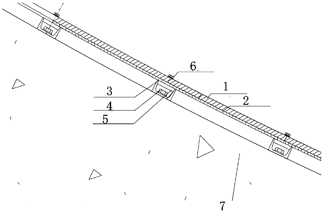
[0027] like figure 1 As shown, a new type of electromagnetic shielding structure under the strong electromagnetic environment of a giant hydroelectric generator is characterized in that it includes a multi-layer silicon steel sheet 2 and a layer of aluminum plate 1 that are stacked and laminated in parallel; the multi-layer silicon steel sheet 2 and a layer The aluminum plates 1 are sequentially stacked and fixedly connected to form an integrated shielding structure; a plurality of channel steels 3 are evenly arranged on the surface of the machine pit wall opposite to the copper bar 9, and the shielding structure is arranged parallel to the machine pit wall and fixedly connected to the channel steel 3; The silicon steel sheet 2 is...


PUM


Abstract

The invention provides a novel electromagnetic shielding structure of a giant hydro-generator in a strong electromagnetic environment. The novel electromagnetic shielding structure comprises multiplelayers of silicon steel sheets and a layer of aluminum plate which are overlapped and laminated in parallel, the multiple layers of silicon steel sheets and the layer of aluminum plate are sequentially laminated and fixedly connected to form an integrated shielding structure; multiple pieces of channel steel are uniformly arranged on the surface of the pit wall opposite to a copper bar, and the shielding structure is parallel to the pit wall and is fixedly connected with the channel steel; the silicon steel sheets are close to the pit wall, and the aluminum plate is close to the copper bar; the silicon steel sheets construct an ultrahigh magnetic conduction path in the space range of the leakage magnetic field, and the distribution of the space magnetic field is changed, so that the leakage flux intentionally entering the reinforcing steel bar enters the silicon steel sheets; and magnetic lines of force vertically penetrate through the aluminum plate to enter the silicon steel sheets,current is induced in the aluminum plate, and the induced current also generates reverse magnetic flux leakage to counteract magnetic flux leakage generated by the original copper bar. The novel electromagnetic shielding structure is used for preventing the conditions of overheating caused by a reinforced concrete structure in the pit wall in the strong electromagnetic environment, structural strength reduction caused by the overheating and the like.

Description

technical field [0001] The invention relates to the technical field of electromagnetic shielding in a generator pit wall, in particular to a novel electromagnetic shielding structure in a strong electromagnetic environment of a giant hydroelectric generator. Background technique [0002] The hydroelectric generator is arranged in the wall of the machine pit, and the wall of the machine pit is a reinforced concrete structure. The main lead wire of the generator needs to be led out of the machine pit wall through copper bars and cables. The rated current of the generator flows through the main center lead, and the current will form a magnetic field. The alternating magnetic field will form eddy currents in the surrounding metal components including the steel bars in the pit wall. Problems such as aging and accelerated aging will affect the safe and stable operation of the entire power station. [0003] In small and medium-sized units, due to the small capacity and low rated ...

Claims


Application Information

Patent Timeline
Patent Type & Authority Applications(China)
IPC IPC(8): H02K3/42
CPCH02K3/42H02K2213/03
Inventor 刘亚青朱钊梁波王树清李璇杨杰欧阳友
Owner CHANGJIANG SURVEY PLANNING DESIGN & RES
Why Eureka
Try Eureka