Hydraulic reversing valve and hydraulic reversing device

A technology of hydraulic reversing valve and valve sleeve, which is applied to valve device, fluid pressure actuating device, valve operation/release device, etc. High frequency commutation requirements and other issues to achieve the effect of high commutation efficiency

Pending Publication Date: 2019-12-10
上海羿弓氢能科技有限公司
View PDF0 Cites 3 Cited by
  • Summary
  • Abstract
  • Description
  • Claims
  • Application Information

AI Technical Summary

Problems solved by technology

[0003] The reversing frequency of the actuators of some equipment is high, and the existing spool type reversing valve has a relatively low reversing frequency due to inertia, which cannot meet the high frequency reversing requirements of the equipment.

Method used


Image

  • Hydraulic reversing valve and hydraulic reversing device
  • Hydraulic reversing valve and hydraulic reversing device
  • Hydraulic reversing valve and hydraulic reversing device

Examples


Embodiment

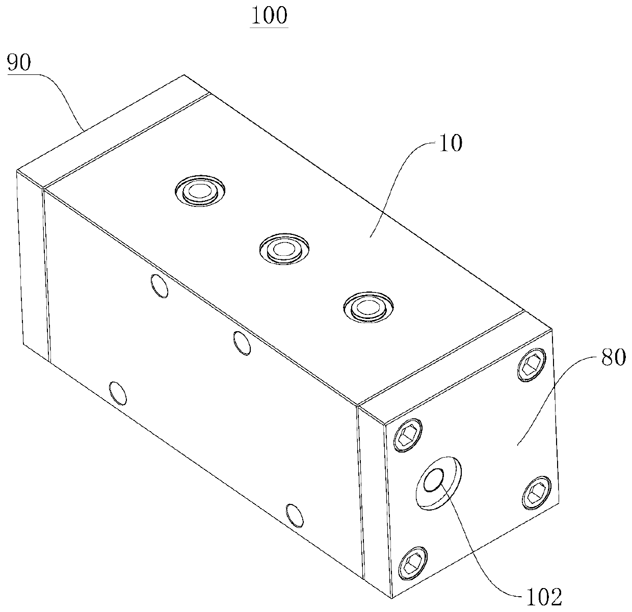
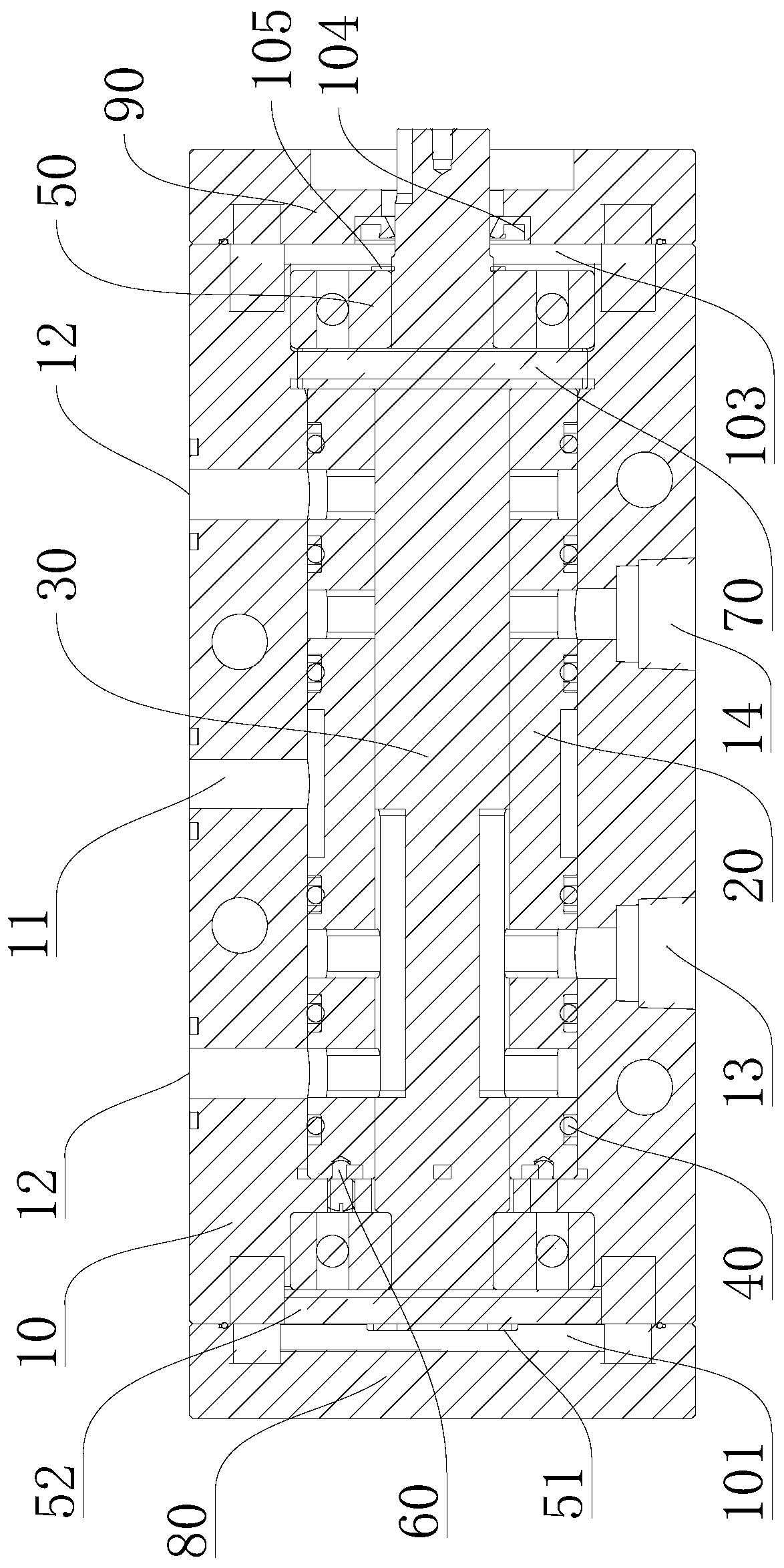
[0052] Please refer to Figure 1 to Figure 7 , this embodiment provides a hydraulic reversing valve 100, including: a valve body 10, a valve sleeve 20 and a valve core 30;

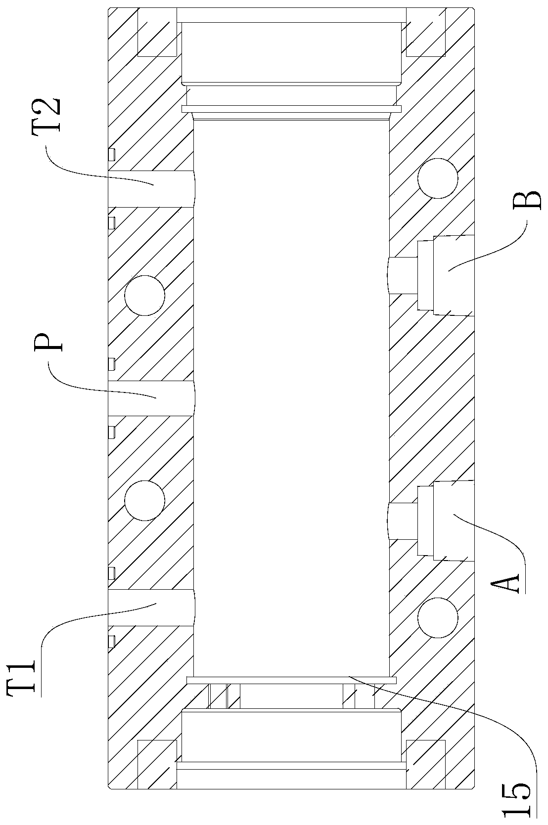
[0053] The interior of the valve body 10 has a first installation chamber, and the valve body 10 also includes a pressure oil port 11 communicating with the first installation chamber, an oil return port 12, a first working port 13 and a second working port 14, and a valve sleeve 20 set in the first installation chamber;

[0054] There is a second installation chamber inside the valve sleeve 20, and a plurality of oil grooves are opened in the circumferential direction of the valve sleeve 20, and the plurality of oil grooves are all provided with liquid passage holes 25 communicating with the second installation chamber. The pressure oil channel 21 communicated with the pressure oil port 11, the switching oil channel 22 communicated with the working port, and the oil return channel 23 communicated with th...


PUM


Abstract

The invention provides a hydraulic reversing valve and a hydraulic reversing device, and relates to the technical field of reversing valves. The hydraulic reversing device comprises a valve body, a valve sleeve and a valve element. The valve body is provided with a first installing cavity and further comprises a pressure oil port, an oil return port, a first work port and a second work port whichcommunicate with the first installing cavity, and the valve sleeve is arranged in the first installing cavity. The valve sleeve is provided with a second installing cavity, the valve sleeve is provided with a plurality of oil grooves in the circumferential direction, and the multiple oil grooves are provided with liquid passing holes communicating with the second installing cavity. The valve element comprises a first liquid passing groove and a second liquid passing groove which are distributed in the axial direction, and the valve element is rotationally arranged in the second installing cavity. The hydraulic reversing valve can meet the usage requirements for the high reversing frequency and high work pressure of execution mechanisms of some devices through combination of the valve body,the valve sleeve and the valve element, cooperation of the liquid passing grooves and the liquid passing holes in the oil grooves and gap seal between the valve element and the valve sleeve. The hydraulic reversing device is formed by the hydraulic reversing valve and a drive mechanism, and the usage requirements can be met as well.

Description

technical field [0001] The present application relates to the technical field of reversing valves, in particular to a hydraulic reversing valve and a hydraulic reversing device. Background technique [0002] In the field of hydraulic engineering, directional valves are widely used. [0003] The reversing frequency of the executive mechanism of some equipment is high, and the existing spool valve reversing valve has a relatively low reversing frequency due to inertia, which cannot meet the high frequency reversing requirements of the equipment. Contents of the invention [0004] The purpose of the present application is to provide a hydraulic reversing valve, which can meet the working requirements of high-pressure working environment and high reversing frequency. [0005] Another object of the present application is to provide a hydraulic reversing device, which includes the above-mentioned hydraulic reversing valve, which can also meet the working requirements of high-pr...

Claims


Application Information

Patent Timeline
Patent Type & Authority Applications(China)
IPC IPC(8): F16K31/04F16K11/085F16K27/06F15B13/02
CPCF15B13/02F16K11/0856F16K27/065F16K31/041
Inventor 陈剑满延范周金跃
Owner 上海羿弓氢能科技有限公司
Why Eureka
Try Eureka