
Neutral point control device for plunger pump

A technology of control device and neutral point, which is applied in pump control, liquid variable displacement machinery, machine/engine, etc. It can solve the problems of inconvenient debugging, inaccurate midpoint of plunger pump, and unguaranteed accuracy, etc., and achieve operation Stability, reasonable structure, and the effect of ensuring the accuracy of equipment use

Inactive Publication Date: 2019-12-10
MASALTA ENG HEFEI
View PDF4 Cites 0 Cited by
  • Summary
  • Abstract
  • Description
  • Claims
  • Application Information

AI Technical Summary

Problems solved by technology

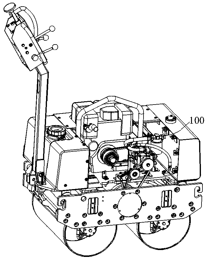
[0002] There is a semi-hydraulic double-steel road roller in the existing market. The front and rear wheels need a plunger pump to provide power through the fluid. At the neutral position, the plunger pump is at idle speed, and the roller stops immediately. However, because the hydraulic control in the plunger pump is extremely sensitive, many plunger pumps on the market do not have a neutral limit function and cannot automatically return to the position. From the position to the middle point, the plunger pump must be controlled by an external mechanical mechanism, which causes many problems. At present, there are many shortcomings in many mechanical structures, such as serious car slipping, inconvenient debugging, and difficult after-sales maintenance.
[0003] At present, there is a kind of plunger pump controlled by the position of the operating rod on the control armrest in the market, but because the push-pull flexible shaft between the operating rod and the plunger pump is relatively long, the error of the assembly gap is relatively large, and the accuracy cannot be guaranteed. It is very confusing, and it is very inconvenient to debug. Even if the adjustment is in place, the push-pull flexible shaft will be deformed and loose after the equipment has been running for a period of time. This will cause the center point of the plunger pump to be inaccurate, and the car will still slip.

Method used


Image

  • Neutral point control device for plunger pump
  • Neutral point control device for plunger pump
  • Neutral point control device for plunger pump

Examples


Embodiment 1

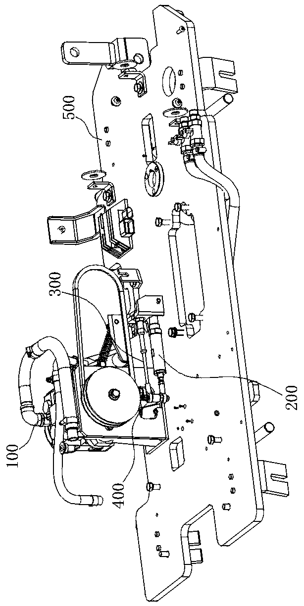
[0035] refer to Figure 1-3, in the embodiment of the present invention, a plunger pump neutral point control device is proposed. The neutral point control device is installed on the tray 500 and connected with the plunger pump 100 on the tray 500. The plunger pump 100 is equipped with a rotating shaft. The rotating shaft is connected to the adjustment mechanism, and the adjusting mechanism adjusts the oil circuit movement direction of the plunger pump 100 by driving the rotating shaft to rotate. When the rotating shaft rotates to the neutral position, the plunger pump 100 is in an idle state, including the energy storage mechanism 200, which is connected to the rotating shaft When the adjusting mechanism adjusts the rotation of the rotating shaft, the rotating shaft drives the energy storage mechanism 200 to run and stores potential energy in the energy storage mechanism.

[0036] Through the setting of the energy storage mechanism 200, when the adjustment mechanism adjusts t...


PUM


Abstract

The invention relates to a neutral point control device for a plunger pump, wherein the neutral point control device is installed on a tray and connected to the plunger pump on the tray, the plunger pump is equipped with a rotating shaft that is connected to an adjusting mechanism, the adjusting mechanism drives the rotating shaft to rotate to adjust the oil circuit movement direction of the plunger pump, the plunger pump is in an idle state when the shaft is rotated to the neutral position, an energy storage mechanism is included and is connected to the rotating shaft, the rotating shaft drives the energy storage mechanism to run and potential energy is stored in the energy storage mechanism when the adjustment mechanism adjusts the rotation of the rotating shaft, and the release of the potential energy in the energy storage mechanism drives the rotating shaft to return to the neutral position when the adjustment mechanism cancels the adjustment of the rotation of the rotating shaft.The invention has a novel structure, reasonable layout and stable operation, can realize the control of neutral point of the rotating shaft of the plunger pump, has the advantages of convenient installation, accurate accuracy and long service life, and meets current requirements for use.

Description

technical field [0001] The invention relates to the field of plunger pump control, in particular to a plunger pump neutral point control device. Background technique [0002] There is a semi-hydraulic double-steel road roller in the existing market. The front and rear wheels need a plunger pump to provide power through the fluid. At the neutral position, the plunger pump is at idle speed, and the roller stops immediately. However, because the hydraulic control in the plunger pump is extremely sensitive, many plunger pumps on the market do not have a neutral limit function and cannot automatically return to the position. From the position to the middle point, the plunger pump must be controlled by an external mechanical mechanism, which causes many problems. At present, there are many shortcomings in many mechanical structures, such as serious car slipping, inconvenient debugging, and difficult after-sales maintenance. [0003] At present, there is a kind of plunger pump con...

Claims


Application Information

Patent Timeline
IPC IPC(8): F04B49/00F04B49/02
CPCF04B49/00F04B49/02
Inventor 胡宏高先来
Owner MASALTA ENG HEFEI
Learn More